Pump Operations
Pump Operations. Amsterdam Fire Regular Fire Training February 16, 2009. Adapted From Cody Fire School Presentations. Purpose and Goals. Review for qualified Driver Operators (DO’s) Preliminary for newer DO’s Preparation for hands on training in March Good common Fire Service knowledge

Pump Operations
E N D
Presentation Transcript
Pump Operations Amsterdam Fire Regular Fire Training February 16, 2009 Adapted From Cody Fire School Presentations
Purpose and Goals • Review for qualified Driver Operators (DO’s) • Preliminary for newer DO’s • Preparation for hands on training in March • Good common Fire Service knowledge • Outline basics of pump operations • Considerations for the DO regarding • Safety • Procedures • Pressure • Variables of water delivery systems.
Safety • Apparatus Placement • Outside the collapse and hot zone • Adequate space to open compartments and connect lines • Supply considerations – Porta-tank, Tender, Hydrant • Power lines • Scene visibility
Safety • Pressure • Inadequate pressure to an interior attack line can put that crew in danger of being overrun by fire. • Over pressuring hand lines makes them difficult to control and may result in injury from free lines. • Pressure relief valve • Equipment damage – guidelines for most pump operations (i.e. sprinkler/fdc, direct tender, relay)
Safety • Operational • Traffic – any active incident scene should have traffic shut down with at least one lane free for the apparatus. • Weather: water + cold = ice. Engine area becomes wet and dangerous, lines freeze. • Equipment – Engine and pump are working under load and more opportunity for equipment to fail causing injury to DO. Broken fittings, engine fires, electrical.
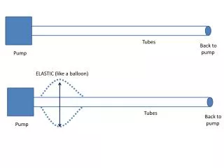
Water Hammer • Water moving through a pipe or hose has both weight and velocity. • The weight of water increases as the pipe or hose size increases. • Suddenly stopping water moving through a hose or pipe results in an energy surge being transmitted in the opposite direction, often many times the original pressure. • Damage to hose, pump, water system and appliances can occur when a water hammer happens.
Examples / Discussion • Describe an incident you have been at where the above safety precautions were not taken, and any adverse effects that resulted.
Getting to Know (and love) Your Apparatus • Engine 9-1: Primary Structure Engine • Carries one DO plus three crew • 1250 GPM primary single stage pump • 1000 Gal Booster tank • Secondary pump for pump and roll (wild land) • Compressed Air Foam System (CAFS) • Generator for scene lighting and tools • General EMS gear • Stabilization equipment
Engine 9-1 cont. • Starting the Pump: • Set parking brake • Place transmission into Neutral (N) • Engage pump transfer switch • Place transmission into Drive (D) • Exit the Engine and set wheel chocks • Open tank to pump and tank refill valves • Turn on foam and compressor
Tender 9-5 • Secondary structure engine • Carries one DO and one crew • 750 GPM pump • 3000 Gal tank capacity • Generator for scene lighting and tools
Tender 9-5 Cont. • Starting the pump: • Set the parking brake • Place transmission into Neutral (N) • Flip PTO electric rocker switch • Exit the cab • Place wheel chocks • Open tank fill and tank to pump valves
Tender 9-4 • Carries one DO and two crew • 350 GPM pump • 1500 gal tank • PTO powered pump for pump and roll • Note – engines pump in drive • Wild land equipment • Portable pump • Portable light / generator
Tender 9-4 cont. • Starting the Pump • Set parking brake • Hold foot on service brake • Leave transmission in Drive (D) • Pull PTO lever slowly until pump engages • Place transmission into Neutral (N) • Exit and open tank to pump and tank fill valves
Disengaging pumps • Throttle down to idle • Ensure parking brake is still set • 9-1 • Place transmission into Neutral (N) • Disengage pump • 9-4 • Place trans into Drive (D) – slows engine • Push PTO lever until pump is disengaged • Place transmission into Neutral (N) • 9-5 • turn off electric rocker switch
Review: • Discuss the difference between PTO and Transmission powered pumps. • Why Wheel Chocks? • When do you shut down pumps?
Pumping Procedure: hydrant supply • Supply line is connected and air bled from line (valve is still closed) • Slowly close tank to pump line while opening incoming supply line
Pumping Procedure: hydrant supply • Now supply is from fire hydrant. • Adjust throttle to allow for incoming pressure
Pumping Procedure: hydrant supply • Slowly refill booster tank while maintaining flow to attack lines • Observe water level gauge to monitor tank level.
Pumping Procedure: Drafting • Hard suction hose is connected to inlet and submerged in water source. Strainer should be covered by @ 2 ½ times the diameter of the hose. • Inlet valve is opened
Drafting Cont. • Priming valve is pulled to expel air from the suction hose. Atmospheric pressure will push water into the fire pump. • Slowly throttle up to desired pump pressure
Drafting Cont. • Connections should be air-tight • Ensure drain valves are closed • Ensure that a discharge is being used to keep water flowing once draft is established. • If tank water permits, use it to backfill the suction line (check valves will inhibit this).
Drafting from uncontained sources (ponds, streams, etc.) With air leaks, friction loss, and pump performance, 10-15’ is a conservative estimate. • 1 gallon = 231 cubic inches, 8.345 pounds • Atmospheric pressure 12.4 lb/in sq at 4500 ft elevation • 14.7 / 8.345 = 1.76 gallons * 231 cubic inches = 406.91 / 12 = 33.9 ft Sea Level • 12.4 / 8.345 = 1.49 gallons * 231 cubic inches = 343.25 / 12 = 28.60 ft Churchill
Direct Tender or Relay • Structure engine receives Water supply from another apparatus. • Supply apparatus at 50psi. • Direct tender connection allows for immediate access to water for initial attack. • Relay pumping allows for: • driveway lays • overcoming height / elevation • consolidating various sources
Water Supply Review • What is the expected pressure range from a municipal water supply? • What is the most common difficulty experienced when drafting? • How much pressure should be delivered by a tender or relay pumper to the target apparatus?
Impeller Pumps (cont.) • Water enters the eye of the impeller • Then it enters the vanes which throws the water to the outside of the impeller. • The impeller is off-center in the casing
Impeller Pumps (cont.) • The centrifugal pump consists of two parts: an impeller and a casing. • The impeller transmits energy in the form of velocity to the water. • The casing collects the water and confines it in order to convert the velocity to pressure. • Then the casing directs the water to the discharge of the pump.
Impeller Pumps (cont.) • Cannot draft - not air tight. • Pressure is additive – front end pressure is added to pressure created by pump. • Cavitation can damage the impeller – caused by attempting to pull more water than available to the pump or introducing air to the supply. Sounds like rocks in the pump.
Rotary Pumps (cont.) • Most common type of primer pump on apparatus. • Oil is often injected into the pump chamber to help seal the gears or vanes.
Fire Pumps (two stage - volume) • Pumping in the parallel (volume) position • When the transfer valve is in the volume position, each impeller receives 50% of the water which when combined the volume is equal to the sum of each of the stages. • A 1,000 gpm (2) stage pump receives 500 gallons to the pump manifold from each impeller.
Fire Pumps (two stage - pressure) • Pumping in the series (pressure) position • When the transfer valve is in the pressure position, all water from the intake manifold is directed to the eye of the 1st impeller. • This stage increases the pressure which is then directed to the eye of the 2nd impeller, thus doubling the pressure. • In series position about 50 -70% of the pump capacity can be used.
Review • Identify the pump types in use on all the apparatus.
Pressure • All apparatus alter pressure with throttle and valves. • Low volume pumps more affected by valves • High volume pumps more affected by throttle • Different applications require different pressure delivery • Master stream • Handline • Spinkler / FDC • EVERYTHING between the pump and the end of the hose affects pressure
Pump Discharge Pressure = Nozzle Pressure + (Total Pressure Loss) PDP = NP+(FL+DL+EL) NP = Nozzle Pressure FL = Friction Loss DL = Device Loss EL = Elevation Loss
Nozzle Pressure • Nozzles consist of handline (50 – 350 gpm) and master stream (350 gpm up) • Nozzles include smooth bore, combination, and specialty (cellar, chimney, piercing, and foam) • The handline smooth bore operates @ 50 psi. • The master smooth bore operates @ 80 psi. • Combination nozzles are intended to be operated at 100 psi • CAFS – smooth bore 75psi
Total Pressure Loss • Total pressure loss is comprised of the following: • Friction loss in various sizes and lengths of fire hose + losses or gains in elevation (#’s of stories in a building or elevation of hills or gullies) + losses in hose appliances (gated wyes, portable monitors, etc.)
Friction Loss The fire service definition of friction loss is that part of the total pressure lost while forcing water through pipe, fittings, fire hose, and adapters. In a fire hose, the following causes friction loss: • Movement of water molecules against each other • Linings in fire hose • Couplings • Sharp bends • Change in hose size or orifice by adapters • Improper gasket size
Reducing Friction Loss • Hose length • Hose Diameter • Sharp bends (kinks) in the hose • Adding additional lines
Friction Loss by Calculation • FL = CQ2L • Where: • FL = Friction loss in psi • C = Friction Loss coefficient • Q = Flow rate in hundreds of gpm (flow/100) • L = Hose length in hundreds of feet (length/100)
Exercise • Determine Friction loss of all pre-connected lines on Engine 9-1 (assume 150gpm for hand lines, 300gpm for 2.5 or 3” lines).
Appliance Pressure Loss • Hoseline appliance such as gated wyes, reducers, increasers, manifolds, aerial apparatus, and standpipe systems. • We will assume a 0 psi loss for flows less than 350 gpm and a 10 psi for each appliance (other than master stream) flowing more than 350 gpm. • Add 25 psi for all Master Streams