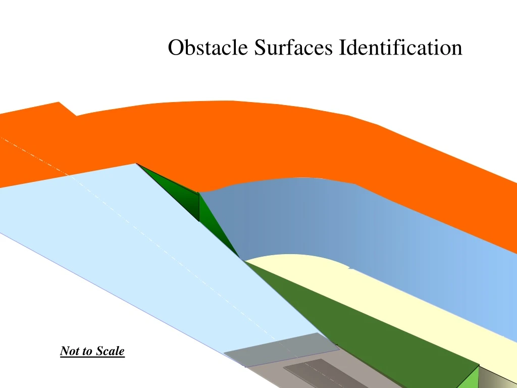
Aerodrome Obstacle Surfaces Identification Not to Scale
250 likes | 352 Views
This document outlines the specifications for identifying obstacles on aerodrome lateral surfaces as per ICAO Annex 14. It covers transitional, inner horizontal, conical, and outer horizontal surfaces. It also details the approach/departure surfaces, runway strips, and other safety areas. The guidelines help determine and manage obstacles in proximity to runways to ensure aviation safety.

Aerodrome Obstacle Surfaces Identification Not to Scale
E N D
Presentation Transcript
Obstacle Surfaces Identification Not to Scale
ICAO Specs ICAO Annex 14 TO THE CONVENTION ON INTERNATIONAL CIVIL AVIATION, VOLUME I, AERODROME DESIGN AND OPERATIONS,
Lateral Surfaces Not to Scale
Runway Not to Scale
Runway Strip and Runway End Safety Area For the purposes of determining obstacles on the sides of the runway, the Runway Strip is referenced horizontally to the runway ends and vertically to the highest threshold on the facility. It extends 300m (240m beyond 60m strip) from each runway end and 150m on either side of the centerline. Not to Scale 150m 300m 150m
Transitional Surface The transitional surfaces extend outward (perpendicular to the centerline of each runway) from the edges of the Runway strip 315m, at a 1:7 slope upward to a height 45m above the published reference elevation of the aerodrome 45m above the published reference elevation of the aerodrome Transitional 45m 1 : 7 Slope 315m 465m Not to Scale
C L Inner Horizontal Surface The inner horizontal surface for each runway is defined by 2 half circles centered on the runway ends and joined by tangents. The radii of the half circles is 4000m and the tangents are parallel to the runway centerline at a distance of 4000m. The surface is a constant 45m above the published reference elevation of the aerodrome 45m above the published reference elevation of the aerodrome Inner Horizontal 4000m 4000m Not to Scale
C L 150 m above the published reference elevation of the aerodrome Conical Conical Surface 6100m The inner edge of conical surface for each runway begins at the outer edge of the inner horizontal surface. Its outer edge is defined by 2 half circles centered on the runway ends and joined by tangents. The radii of the half circles is 6100 m and the tangents are parallel to the runway centerline at a distance of 6100 m. The surfaces extend 2100 m horizontally and are sloped at a 1:20 ratio. The outer edge is 150 m above the height of the published reference elevation of the aerodrome 6100m 150m 1:20 Slope 4000m 2100m Not to Scale
C L Outer Horizontal 8000m 8000m Outer Horizontal Surface 150m The Outer Horizontal surface begins at the outer edge of the conical surface and extends outward to a distance of 8000 m from the endpoints and centerline of the runway at a constant height of 150 m above the published reference elevation of the aerodrome Not to Scale
C L Outer Horizontal Conical Recap of Lateral Surfaces Inner Horizontal Transitional Runway Strip Not to Scale
Approach/Departure Surfaces 15% divergence (9 Degrees) 240m min RESA – runway end safety area Not to Scale
Runway Strip and Clearway For the purposes of determining obstacles on the sides of the runway, the Primary Surface is referenced horizontally to the runway ends and vertically to the highest threshold on the facility. It extends 300 m from each runway end and 150 m on either side of the centerline. For the purposes of determining obstacles in the approach/departure zones, the horizontal and vertical point of reference is the runway Threshold Not to Scale 150m 300 m 150m
Approach/Departure Surfaces 1:50 Surface vertical reference is the height of the runway threshold 150m Above lowest Runway end on airport 1:50 Slope 15 000m ~8 000m 300m 1:50 Surface horizontal reference is 60 m from the runway end Not to Scale
C L At the end of the runway 60 m The runway and stopway is included in the runway strip 150m Runway strip 150m Runway strip 60 m Not to Scale
If no object reaches the 2 percent (1:50) take-off climb surface, new objects shall be limitedto preserve the existing obstacle free surface or a surface downto a slope of 1.6per cent (1:62.5). The 1:50 Sloped surface Side view 150 m above the lowest approach end on the airport First section extends to 3000m Threshold 1:50 ( 1:62.5) Slope Height of approach end 60 m ~8 000m Not to Scale
At the end of the runway 150m 300m 150m 60m Not to Scale
The 1:50 Sloped surface Not to Scale 150m above the lowest approach end on the airport 150m 300m 150m Not to Scale
At the end of the runway Side View Not to Scale 150M above the lowest approach end on the airport Threshold 1:50 Slope 60 m ~8 000m 15 000m
The “flat” approach departure surface Not to Scale 150m above the lowest approach end on the airport 150m 300m ~8 000m 150m ~15 000m
Approach/Departure Surfaces 1:50 Surface vertical reference is the height of the runway end point 150m Above lowest approach end on airport 1:50 Slope 15 000m ~8 000m 300m 1:50 Surface horizontal reference is 60m from the runway end Not to Scale
+ Transitional Not to Scale
+ Inner Horizontal Not to Scale
+ Conical Not to Scale
+ Outer Horizontal Not to Scale
Obstacle Identification Surfaces Not to Scale