Advanced Seismic Reflection Modelling for Hydrocarbon Reservoirs
260 likes | 348 Views
Explore the complexities of seismic reflection in sedimentary basins, focusing on hydrocarbon reservoirs. Learn about the challenging forward and inverse problems in modelling wave equations and Green functions. Discover methods used in reflection seismic with examples. Unravel the significance of ray tracing and seismic ray theory in these geological settings. Understand how seismic data processing and interpretation help identify structural traps for hydrocarbon accumulation. Delve into the mathematical foundations of seismic modelling to address complex structures and challenges in the industry.

Advanced Seismic Reflection Modelling for Hydrocarbon Reservoirs
E N D
Presentation Transcript
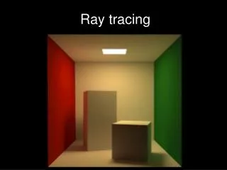
1. Ray-tracing modelling • Reflection seismic • The seismic forward and inverse problem • Wave equation, Green function, ansatz • The eikonal equation • The transport equation • Methods • Examples
Reflection seismic • Hydrocarbon reservoirs are typically found in sedimentary basins, at depths of the order of a few kilometres. The most commonly applied and successful experiment in this geological setting is the seismic reflection experiment, in which both sources and receivers are spread out on the surface. The success of the reflection experiment is primarily due to the typically layered structures of sedimentary basins, which reflect (scatter) seismic waves generated at the source back to the surface, where they are recorded by the receivers.
Reflection seismic • Despite the relative placidity of the environments in which sedimentation usually takes place, sedimentary basins can exhibit very complex structures. These are usually caused by later tectonic events such as folding, faulting and intrusion of salt or basalt. Complex structures are often the most interesting part of such a subsurface because these may contain structural traps that give rise to accumulation of hydrocarbons. The processing and interpretation of seismic data in complex structures are difficult and remain a challenge.
The seismic inverse problem • In mathematical terminology the problem of transforming the seismic measurements, the data, into a set of quantitative subsurface properties – the model (parameters) – Is called an inverse problem. As indicated by its name, the inverse problem has a counterpart: the forward problem. This problem concerns the expression of data in terms of the model parameters by means of a mathematical model for the physics involved in the experiment. The methodology used for solving the inverse problem relies strongly on the formulation of the forward problem.
The seismic inverse problem • For most practical situations in seismics, the earth may be considered to be an elastic medium. The elastic wave equation should therefore be an adequate mathematical model for the forward problem. In general, however, the relationship between a solution of the wave equation (the measured data) and its coefficients (the model parameters) is strongly non-linear. This non-linearity makes the inverse problem very hard to be tackled directly.
The seismic inverse problem • A common approach to addressing such non-linear inverse problems is by means of perturbations. The model parameters sought are then defined to be small perturbations to a known (reference) model. The forward problem can then be linearised, thereby facilitating the corresponding inverse problem. In reflection seismics a practical approach is to define a smooth reference model and consider sharp features, such as interfaces and faults, as the perturbations to be inverted for. Some common terms that are used for this kind of inversion are migration, imaging, and inverse scattering. The latter name relates to the interpretation that the sharp features act as scatterers of the wave field propagating in the smooth reference model.
The seismic inverse problem • The most challenging aspect of the inversion of seismic reflection data is, probably, to determine the smooth reference model for which the linearised inverse scattering procedure may give a reliable result. This procedure is also known as velocity analysis and is typically done by means of tomography. Whereas the inverse scattering is usually a one step procedure, the tomographic inversion requires iteration. The quality of updates in the reference model is usually estimated by means of a measure of the coherency (focusing) of the result of the inverse scattering.
Ray tracing. Introduction • Seismic ray theory borrows much of its principles and methodology from electromagnetic ray theory, or geometric optics as it is usually called (Born and Wolf, 1980; Kline and Kay, 1965). There are two major approaches to the derivation of the ray equations. The first, classical approach is based entirely on heuristic geometric principles and is therefore called geometric ray theory. The second approach derives the ray equations from the wave equation by means of asymptotic analysis. This approach is referred to as asymptotic ray theory.
Ray tracing. Introduction • Geometric ray theory has played a prominent role in the history of natural science, as a practical theory to explain the propagation of light. Both the rectilinear propagation of light and the law of reflection were described by Euclid already around 300 BC. The most important steps were made in the seventeenth century with Snell’s law of refraction and Fermat’s principle of least time. The subsequent statement of similar geometrical principles in classical mechanics finally led to an extensive mathematical theory associated with the names of Euler, Lagrange, Jacobi and Hamilton (e.g., Lanczos, 1986; Goldstein, 1980).
Ray tracing. Introduction • Apart from establishing ray theory as a high frequency asymptotic approximation, the asymptotic analysis also extended ray theory to explain a wider range of wave phenomena. Whereas geometrical ray theory formally explains only ray paths and travel times, asymptotic ray theory also provides a theoretical basis for the calculation of amplitudes and polarisation. Moreover, ray theory in anisotropic media is much easier to derive from asymptotic analysis than from geometric principles (although it is possible to do so, see (Cerveny, 2002). Seismic ray theory in general elastic media has been based on high frequency asymptotics from its inception (Babich, 1994; Cerveny, 1972).
Wave equation • The basic assumption underlying all of the following is that the physical properties of the media under consideration are adequately described in terms of linear elastodynamics. In that case the combination of Newton’s equation of motion and Hooke’s law of linear elasticity (both generalised to continuous media) yields the wave equation. (1.1) with solution (1.2)
Homogeneous medium (1.3) (1.4)
Fourier transform revisited(you are supposed to know that) Wave equation example:
Helmholtz equation • After Fourier transform equation (1.1) becomes (1.5) with solution (1.6)
Helmholtz equation • Substituting equation (1.6) into equation (1.1) results in (1.7)
Eikonal equation • The real part of equation (1.7) gives (1.8) For high frequencies we can neglect first term (1.9)
Transport equation • The imaginary part of (1.7) gives (1.10)
Snell’s law • To compute rays we also need (1.11) I R q T
Methods • Asymptopic (Ursin and Dahl, 1992) • Pseudo-spectral (Chapman. 2002) • Intrapolation (Vanelle and Gajewski, 2002) • Ray field construction (Cerveny et al., 1981)
Examples Figure 1.1: Ray fields corresponding to a source at x = 1.5, calculated using wave front construction. Figure (a) shows the ray field in a homogeneous medium with slowness 1.0, Figure (b) the one for a Gaussian slowness anomaly of magnitude +0.3 superimposed on the homogeneous background of Figure (a). The anomaly causes triplication in the ray field.
More examples Figure 1.2: Four examples of the ray field construction algorithm. Figure (a) shows the ray field in a homogeneous medium. Figure (b) shows three partial quasi-P wave fronts in a homogeneous 3-D medium. The medium is anisotropic: VTI with Thomsen parameters VP = 1.0, VS = 0.6, o = -0.2, δ = 0.2, and γ = 0.0. Figure (c) and (d) show ray fields in a 2-D VTI medium with a Gaussian anomaly. The Thomsen parameters of the isotropic background are VP0 = 1.0, VS0 = 0.6, o0 = 0.0, δ0 = 0.0, and γ0 = 0.0; the anisotropic Gaussian anomaly has parameters VP1 = -0.5, VS1 = -0.3, o1 = 0.5, δ1 = 0.0, and γ1 = 0.0. The spatial variation of the anomaly is proportional to exp((-(x - 0.4)2 - (z - 0.4)2)/0.32). Figure (c) and (d) show the quasi-P and quasi-S ray fields respectively. The line segments plotted on a number of wave fronts indicate the polarisation directions.
Ray field sampling Figure 1.3: Ray fields in an isotropic 2-D medium. The velocity V satisfies V = 1 - 0.4 exp(-((x - 0.4)2 + (z - 0.4)2)/0.32), that is, a slow Gaussian shaped anomaly. A caustic is formed in the upper right corner.
Snapshot Vp=4000 м/s, Vs=2310 м/s, =2.350 g/см3 Vp=2000 м/s, Vs=1150 м/s, =2.010 g/см3 Vp=5000 м/s, Vs=2900 м/s, =2.500 g/см3