Download
1 / 53
612 likes | 916 Views
Impedance, Resonance, and Filters. Al Penney VO1NO. A Quick Review…. Before discussing Impedance, we must first understand capacitive and inductive reactance. Reactance. Reactance is the opposition to the flow of Alternating Current (AC).

E N D
Impedance, Resonance, and Filters Al Penney VO1NO
A Quick Review… • Before discussing Impedance, we must first understand capacitive and inductive reactance.
Reactance • Reactance is the opposition to the flow of Alternating Current (AC). • Reactance has no effect on the flow of Direct Current (DC).
Capacitive Reactance • Capacitive Reactance is the opposition to the flow of AC by capacitance. • As the frequency of the AC increases, Capacitive Reactance decreases. • The Symbol for Capacitive Reactance is XC. • XC is expressed in ohms. • Even though it is expressed in ohms, power is not dissipated by Reactance! Energy stored in a capacitor during one part of the AC cycle is simply returned to the circuit during the next part of the cycle!
Capacitive Reactance • Where: F = frequency in Hertz C = capacitance in Farads π = 3.14
Inductive Reactance • Inductive Reactance is the opposition to the flow of current in an AC circuit caused by an inductor. • As the frequency increases, Inductive Reactance also increases. • The symbol for Inductive Reactance is XL. • Even though it is expressed in ohms, power is not dissipated by Reactance! Energy stored in an inductor’s magnetic field during one part of the AC cycle is simply returned to the circuit during the next part of the cycle!
Inductive Reactance • Where: f = frequency in Hertz L = inductance in henrys π = 3.14
Current versus Voltage • In a simple resistive circuit, the current and voltage are always in phase. • For reasons beyond the scope of the Basic Course, the current and voltage are not in phase in AC circuits that contain capacitance and/or inductance. • The current across a capacitor leads the voltage by 90 degrees. • The current across an inductor lags the voltage by 90 degrees.
Vector Representation • When plotted as vectors,series circuits containing Inductance, Capacitance and Resistance (LCR) can be represented as such: XL Inductive Reactance Resistance XC Capacitive Reactance
Inductive vs Capacitive Reactance • Inductive and Capacitive Reactance cannot be added together to give an overall reactance. • In fact, they tend to cancel each other out. XL XL - XC = Resistance Resistance XC
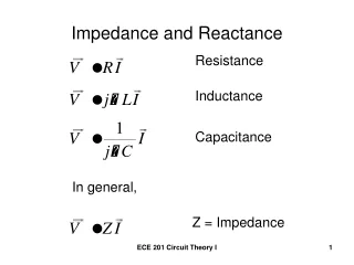
Impedance • When a circuit contains both resistance and reactance, the opposition to the flow of AC is called Impedance, abbreviated Z. • Because Resistance and Reactance are not in phase however, we must use vectors to determine the Impedance, even if Inductive and Capacitive Reactance have partly cancelled each other out.
Vector Addition Through the use of vector addition, the Impedance can be determined… XL - XC Impedance (Z) XL - XC = Resistance Resistance
LCR Circuit Impedance Formula • Rather than plot vectors every time we need to determine impedance however, we can use a formula: • Note that because the difference between XL and XC is squared, it doesn’t matter what term is subtracted from what – you can use XC – XL if that is more convenient. Z
LCR Circuit Impedance Example • Resistance = 120 Ohms • XL = 40 Ohms • XC = 130 Ohms • Z = Sqr Root [ R2 + (XC – XL)2 ]
LCR Circuit Impedance Example • Resistance = 120 Ohms • XL = 40 Ohms • XC = 130 Ohms • Z = Sqr Root [ R2 + (XC – XL)2 ] = Sqr Root [ (120)2 + (130 – 40)2 ]
LCR Circuit Impedance Example • Resistance = 120 Ohms • XL = 40 Ohms • XC = 130 Ohms • Z = Sqr Root [ R2 + (XC – XL)2 ] = Sqr Root [ (120)2 + (130 – 40)2 ] = Sqr Root [ 14400 + 8100 ]
LCR Circuit Impedance Example • Resistance = 120 Ohms • XL = 40 Ohms • XC = 130 Ohms • Z = Sqr Root [ R2 + (XC – XL)2 ] = Sqr Root [ (120)2 + (130 – 40)2 ] = Sqr Root [ 14400 + 8100 ] = Sqr Root [ 22500 ]
LCR Circuit Impedance Example • Resistance = 120 Ohms • XL = 40 Ohms • XC = 130 Ohms • Z = Sqr Root [ R2 + (XC – XL)2 ] = Sqr Root [ (120)2 + (130 – 40)2 ] = Sqr Root [ 14400 + 8100 ] = Sqr Root [ 22500 ] = 150 Ohms
LCR Circuit Impedance Example XL = 40 Ohms Resistance = 120 Ohms XC = 130 Ohms
LCR Circuit Impedance Example XL = 40 Ohms Resistance = 120 Ohms XC - XL = 90 Ohms XC = 130 Ohms
LCR Circuit Impedance Example XL = 40 Ohms Resistance = 120 Ohms XC - XL = 90 Ohms XC = 130 Ohms
LCR Circuit Impedance Example XL = 40 Ohms Resistance = 120 Ohms XC - XL = 90 Ohms Z = 150 Ohms XC = 130 Ohms
Impedance Matching • Many electronic devices and circuits (speakers, microphones, antennas, transmission lines, amplifiers etc.) have their own characteristic impedance. • When interconnecting these devices and circuits, maximum power transfer will take place if the various impedances are matched.
Matching with Transformers • Transformers are often used to match impedances which are primarily resistive. • This is especially true for antenna and transmission line systems. • Take the matching transformer (Balun – BALanced to UNbalanced) used to match 300 Ohms to 75 Ohms in TV systems.
300 – 75 Ohm Balun • These matching transformers are widely used for TV systems, and consist of a small ferrite core with two windings. • In addition to the impedance transformation, it also converts between a balanced system and an unbalanced system.
Number of Turns • Different impedances can be matched quite easily by adjusting the number of turns using the following formula: ZS/ ZP= NS2 / NP2 Or… NS/ NP = √ ZS / ZP
Number of Turns - Example • ZS = 300 Ohms, ZP = 75 Ohms NS/ NP = √ ZS / ZP NS/ NP = √ 300 / 75 = √ 4 = 2 • The turns ratio is 2:1 ie: for every turn on the primary winding, there are two on the secondary winding. • The actual number of turns depends on the core material.
Resonance • In electronic circuits, a special condition exists when Inductive and Capacitive Reactance are equal to each other (XL = XC). • When that happens in Series LCR circuits, XL and XCcancel each other out, leaving only Resistance to oppose the flow of AC current. • This condition is know as Resonance, and occurs at only one frequency, known as the Resonant Frequency (FR).
Resonant Frequency Reactance XL Resonant Frequency XC Low High Frequency
Resonant Frequency • At Resonance, XC = XLso • With a little mathematical wizardry, we can rearrange that equation to determine the Resonant Frequency FRas follows… =
Resonant Frequency • Where: FR = Resonant Frequency in Hertz L = Inductance in henrys C = Capacitance in Farads
Tuned Circuits • Circuits containing Capacitors and Inductors are often referred to as Tuned Circuits. • They have many uses in electronics – every time you tune a radio, you are varying the resonant frequency of a tuned circuit.
Series LCRCircuit • When a Series LCR circuit is in Resonance,current in that circuit is at its greatest (the Impedance is at its lowest). • There are two ways to achieve Resonance in SeriesLCR circuits: • Vary the applied frequency until we find the point where XC = XL. • Keep the frequency constant and vary the value of the capacitance or inductance, or both, until XC = XL.
Varying the Frequency FR Circuit Current Frequency
Varying Capacitance or Inductance FR Circuit Current Frequency
Parallel LCR Circuits • In a Parallel LCR Circuit, the current is lowest at Resonance (the impedance is at its highest). • Parallel LCR circuits are used to reject a specific frequency while allowing all others to pass.
Parallel LCR Circuit Current Resonant Frequency Circuit Current Frequency
Circuit Quality • In a resonant series LCR circuit, energy is stored alternately in the electric field of the capacitor, and then the magnetic field of the inductor. • This causes a current to flow between them. • Anything that removes energy from this circuit broadens the range of frequencies affected by the circuit, but increases the impedance at the resonant frequency.
Circuit Quality • The “Q”, or Quality of a series LCR circuit is defined as the ratio of either XC or XL to the resistance in the circuit. • Below resonance “Q” = XC / R • Above resonance “Q” = XL / R • At resonance XC = XL • A “Q” of 100 is high, while a “Q” of 10 is low.
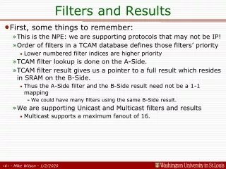
Filters • By the proper selection of capacitors and inductors, it is possible to design Filters that can pass desired frequencies, and reject unwanted frequencies.
I Low Pass Filter Frequency I High Pass Filter Frequency I Band Pass Filter Frequency I Notch Filter Frequency