Download

1 / 31
310 likes | 466 Views
EE360: Lecture 8 Outline Intro to Ad Hoc Networks. Announcements Proposal feedback by Wed, revision due following Mon HW 1 posted this week, due Feb. 22 Overview of Ad-hoc Networks Design Issues MAC Protocols Routing Relay Techniques Generalized cooperation Feedback in Ad-Hoc Networks.

E N D
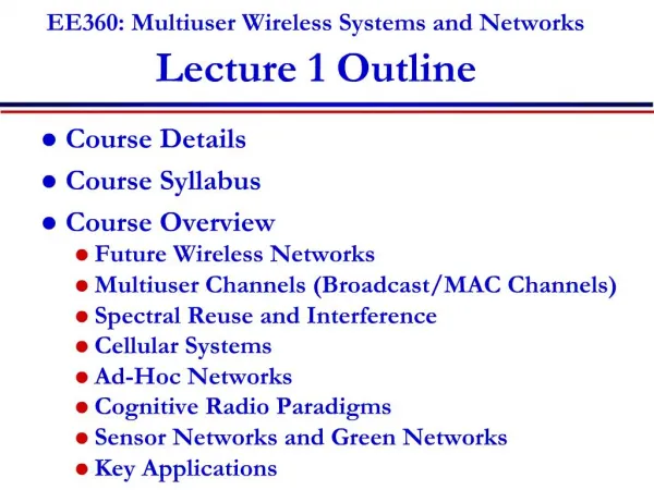
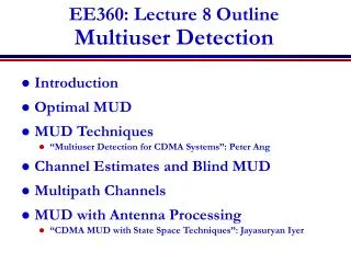
EE360: Lecture 8 OutlineIntro to Ad Hoc Networks • Announcements • Proposal feedback by Wed, revision due following Mon • HW 1 posted this week, due Feb. 22 • Overview of Ad-hoc Networks • Design Issues • MAC Protocols • Routing • Relay Techniques • Generalized cooperation • Feedback in Ad-Hoc Networks
Ad-Hoc Networks • Peer-to-peer communications • No backbone infrastructure or centralized control • Routing can be multihop. • Topology is dynamic. • Fully connected with different link SINRs • Open questions • Fundamental capacity • Optimal routing • Resource allocation (power, rate, spectrum, etc.) to meet QoS
Ad-Hoc NetworkDesign Issues • Ad-hoc networks provide a flexible network infrastructure for many emerging applications. • The capacity of such networks is generally unknown. • Transmission, access, and routing strategies for ad-hoc networks are generally ad-hoc. • Crosslayer design critical and very challenging. • Energy constraints impose interesting design tradeoffs for communication and networking.
Hidden Terminal Exposed Terminal 1 2 3 4 5 Medium Access Control • Nodes need a decentralized channel access method • Minimize packet collisions and insure channel not wasted • Collisions entail significant delay • Aloha w/ CSMA/CD have hidden/exposed terminals • 802.11 uses four-way handshake • Creates inefficiencies, especially in multihop setting
Frequency Reuse • More bandwidth-efficient • Distributed methods needed. • Dynamic channel allocation hard for packet data. • Mostly an unsolved problem • CDMA or hand-tuning of access points.
DS Spread Spectrum:Code Assignment • Common spreading code for all nodes • Collisions occur whenever receiver can “hear” two or more transmissions. • Near-far effect improves capture. • Broadcasting easy • Receiver-oriented • Each receiver assigned a spreading sequence. • All transmissions to that receiver use the sequence. • Collisions occur if 2 signals destined for same receiver arrive at same time (can randomize transmission time.) • Little time needed to synchronize. • Transmitters must know code of destination receiver • Complicates route discovery. • Multiple transmissions for broadcasting.
Transmitter-oriented • Each transmitter uses a unique spreading sequence • No collisions • Receiver must determine sequence of incoming packet • Complicates route discovery. • Good broadcasting properties • Poor acquisition performance • Preamble vs. Data assignment • Preamble may use common code that contains information about data code • Data may use specific code • Advantages of common and specific codes: • Easy acquisition of preamble • Few collisions on short preamble • New transmissions don’t interfere with the data block
Introduction to Routing Destination Source • Routing establishes the mechanism by which a packet traverses the network • A “route” is the sequence of relays through which a packet travels from its source to its destination • Many factors dictate the “best” route • Typically uses “store-and-forward” relaying • Network coding breaks this paradigm
Relay nodes in a route Source Relay Destination • Intermediate nodes (relays) in a route help to forward the packet to its final destination. • Decode-and-forward (store-and-forward) most common: • Packet decoded, then re-encoded for transmission • Removes noise at the expense of complexity • Amplify-and-forward: relay just amplifies received packet • Also amplifies noise: works poorly for long routes; low SNR. • Compress-and-forward: relay compresses received packet • Used when Source-relay link good, relay-destination link weak Often evaluated via capacity analysis
Routing Techniques • Flooding • Broadcast packet to all neighbors • Point-to-point routing • Routes follow a sequence of links • Connection-oriented or connectionless • Table-driven • Nodes exchange information to develop routing tables • On-Demand Routing • Routes formed “on-demand” “E.M. Royer and Chai-Keong Toh, “A review of current routing protocols for ad hoc mobile wireless networks,” IEEE Personal Communications Magazine, Apr 1999.”
Cooperation in Wireless Networks • Routing is a simple form of cooperation • Many more complex ways to cooperate: • Virtual MIMO , generalized relaying, interference forwarding, and one-shot/iterative conferencing • Many theoretical and practice issues: • Overhead, forming groups, dynamics, synch, …
Virtual MIMO • TX1 sends to RX1, TX2 sends to RX2 • TX1 and TX2 cooperation leads to a MIMO BC • RX1 and RX2 cooperation leads to a MIMO MAC • TX and RX cooperation leads to a MIMO channel • Power and bandwidth spent for cooperation TX1 RX1 RX2 TX2
Capacity Gain with Cooperation (2x2) x1 TX1 • TX cooperation needs large cooperative channel gain to approach broadcast channel bound • MIMO bound unapproachable G G x2
Cooperative DPC best Cooperative DPC worst d=r<1 x1 x1 TX1 y2 x2 d=1 Capacity Gainvs Network Topology RX2 Optimal cooperation coupled with access and routing
Relative Benefits ofTX and RX Cooperation • Two possible CSI models: • Each node has full CSI (synchronization between Tx and relay). • Receiver phase CSI only (no TX-relay synchronization). • Two possible power allocation models: • Optimal power allocation: Tx has power constraint aP, and relay (1-a)P ; 0≤a≤1 needs to be optimized. • Equal power allocation (a = ½). Joint work with C. Ng
Example 1: Optimal power allocation with full CSI • Cut-set bounds are equal. • Tx co-op rate is close to the bounds. • Transmitter cooperation is preferable. Tx & Rx cut-set bounds Tx co-op Rx co-op No co-op
Example 2: Equal power allocation with RX phase CSI • Non-cooperative capacity meets the cut-set bounds of Tx and Rx co-op. • Cooperation offers no capacity gain. Non-coop capacity Tx & Rx cut-set bounds
Capacity: Non-orthogonal Relay Channel • Compare rates to a full-duplex relay channel. • Realize conference links via time-division. • Orthogonal scheme suffers a considerable performance loss, which is aggravated as SNR increases. Non-orthogonal Cut-set bound Non-orthogonal DF rate Non-orthogonal CF rate Iterative conferencing via time-division
Transmitter vs. Receiver Cooperation • Capacity gain only realized with the right cooperation strategy • With full CSI, Tx co-op is superior. • With optimal power allocation and receiver phase CSI, Rx co-op is superior. • With equal power allocation and Rx phase CSI, cooperation offers no capacity gain. • Similar observations in Rayleigh fading channels.
Multiple-Antenna Relay Channel • Full CSI • Power per transmit antenna: P/M. • Single-antenna source and relay • Two-antenna destination • SNR < PL: MIMO Gain • SNR > PU: No multiplexing gain; can’t exceed SIMO channel capacity (Host-Madsen’05) Joint work with C. Ng and N. Laneman
Conferencing Relay Channel • Willems introduced conferencing for MAC (1983) • Transmitters conference before sending message • We consider a relay channel with conferencing between the relay and destination • The conferencing link has total capacity C which can be allocated between the two directions
Iterative vs. One-shot Conferencing • Weak relay channel: the iterative scheme is disadvantageous. • Strong relay channel: iterative outperforms one-shot conferencing for large C. One-shot: DF vs. CF Iterative vs. One-shot
Lessons Learned • Orthogonalization has considerable capacity loss • Applicable for clusters, since cooperation band can be reused spatially. • DF vs. CF • DF: nearly optimal when transmitter and relay are close • CF: nearly optimal when transmitter and relay far • CF: not sensitive to compression scheme, but poor spectral efficiency as transmitter and relay do not joint-encode. • The role of SNR • High SNR: rate requirement on cooperation messages increases. • MIMO-gain region: cooperative system performs as well as MIMO system with isotropic inputs.
RX1 TX1 X1 Y4=X1+X2+X3+Z4 relay Y3=X1+X2+Z3 X3= f(Y3) Y5=X1+X2+X3+Z5 X2 TX2 RX2 Generalized Relaying Analog network coding • Can forward message and/or interference • Relay can forward all or part of the messages • Much room for innovation • Relay can forward interference • To help subtract it out
In fact, it can achieve capacity P3 P1 Ps D S P2 P4 • For large powers Ps, P1, P2, analog network coding approaches capacity
How to use Feedback in Wireless Networks Noisy/Compressed Output feedback CSI Acknowledgements Network/traffic information Something else
MIMO in Ad-Hoc Networks • Antennas can be used for multiplexing, diversity, or interference cancellation • Cancel M-1 interferers with M antennas • What metric should be optimized? Cross-Layer Design
Multiplexing Error Prone Diversity-Multiplexing-Delay Tradeoffs for MIMO Multihop Networks with ARQ ARQ ARQ Beamforming H2 H1 Low Pe • MIMO used to increase data rate or robustness • Multihop relays used for coverage extension • ARQ protocol: • Can be viewed as 1 bit feedback, or time diversity, • Retransmission causes delay (can design ARQ to control delay) • Diversity multiplexing (delay) tradeoff - DMT/DMDT • Tradeoff between robustness, throughput, and delay
FLoWS Fundamental Limits of Wireless Systems (DARPA Challenge Program) Network Metrics C B A NetworkFundamental Limits Capacity Delay D Outage Cross-layer Design and End-to-end Performance • Research Areas • Fundamental performance limits and tradeoffs • Node cooperation and cognition • Adaptive techniques • Layering and Cross-layer design • Network/application interface • End-to-end performance • optimization and guarantees Capacity (C*,D*,R*) Delay Robustness Application Metrics
Today’s presentation Apurva will present “User cooperation diversity: Part I. System description”, Sendonaris, A. ; Erkip, E. ; Aazhang, B. ; IEEE Transactions on Communications, vol. 51, pp. 1927-1938, 2003 Required reading (forgot to post)