Download
1 / 13
190 likes | 861 Views
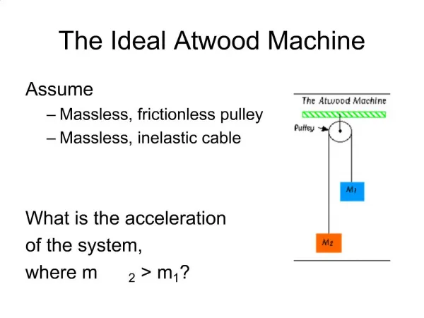
The Atwood Machine. Two masses suspended over a pulley. m 2. m 1. George Atwood. (1746-1807). British scientist that designed the Atwood Machine. Atwood Machine Free Body Diagram. T. T. Newton’s 1 st Law. Constant Velocity. Σ F=0 T-W 1 =0 T-W 2 =0 T=W 1 T=W 2 W 1 =W 2

E N D
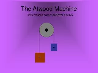
The Atwood Machine Two masses suspended over a pulley. m2 m1
George Atwood (1746-1807) British scientist that designed the Atwood Machine
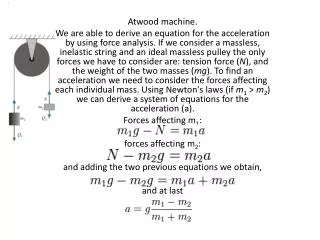
Atwood Machine Free Body Diagram T T Newton’s 1st Law Constant Velocity ΣF=0 T-W1=0 T-W2=0 T=W1 T=W2 W1=W2 W1=m1g W2=m2g g=9.8 m/s2 m1 m2 W2 W1
Atwood Machine Free Body Diagram T T Newton’s 2nd Law Acceleration ΣF=ma T-W1=m1(-a) T-W2=m2(a) T=W1+m1(-a) W1+m1(-a)-W2=m2(a) W1-W2=(m1+m2)(a) or T=W2+m2a W2+m2(a)-W1=m1(-a) W2-W1=(m1+m2)(-a) W1=m1g W2=m2g g=9.8 m/s2 m1 m2 a -a W2 W1
Alternate Atwood Machine Interpretation m2 m1 m1 w1 m2 w2
Alternate Atwood Machine Interpretation m1 w1 m2 w2 Newton’s 1st Law ΣF=0 -W1+W2=0 W1=W2 Newton’s 2nd Law ΣF=ma -W1+W2= (m1+m2)a W2>W1 -W1+W2=(m1+m2)(-a) W2<W1 T W1 m1 T W2 m2 constant velocity T-W2=0 T-W1=0 W1=W2 acceleration T-W1=m1(a) T-W2=m2(a)
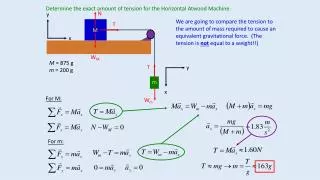
Pulley and Inclined Plane Free Body Diagram T T f m1 m2 W|| N W┴ W2 T-W2=0 const vel T-W2=m2(a) acc up T-W2=m2(-a) acc down Newton’s First Law: ΣF=0 constant velocity (motion or pending motion down) -W||+f+T=0 -W||+f+W2 =0 (const vel) Newton’s Second Law: -W||+f+T=m1(-a) m1 accelerating down the incline -W||-f+T=m1a m1 accelerating up the incline The equations can be combined to give: -W||+f+W2=(m1+m2)(-a) (m1 acc down, m2 acc up) -W||-f+W2=(m1+m2)a (m1 acc up, m2 down)
Alternate Pulley and Inclined Plane Interpretation f W|| m1 m2 W2 -W||+f+W2 =0 (const vel) -W||+f+W2=(m1+m2)(-a) (m1 acc down, m2 acc up)
Pulley Scenario 3 m2 m3 m1
T2 T1 T1 m2 T2 m1 m3 W1 W3 Newton’s 1st Law (constant velocity): T1-W1=0 T1=W1 T2-W3=0 T2=W3 -T1+T2=0 Combining Equations: W1=W3
T2 T1 -a T1 m2 T2 m1 -a m3 +a W3 W1 Newton’s 2nd Law (acceleration): T2-W3=m3(a) T2=W3+m3(a) T1-W1=m1(-a) T1=W1-m1(a) -T1+T2=m2(-a) Combining Equations: -W1+m1(a)+W3+m3(a)=m2(-a) -W1+W3=(m1+m2+m3)(-a)
-a m1 m2 m3 W1 W3 Newton’s 1st Law (constant velocity): Combining Equations: W1=W3 Newton’s 2nd Law (acceleration): T1-W1=m1(-a) T1=W1-m1(a) T2-W3=m3(a) T2=W3+m3(a) -T1+T2=m2(-a) Combining Equations: -W1+m1(a)+W3+m3(a)=m2(-a) -W1+W3=(m1+m2+m3)(-a)