Download
1 / 34
340 likes | 375 Views
Explore ray tracing in optical systems, from stable to unstable cavities, lens properties, wave transformations, and stability diagrams. Learn how to describe, trace, and analyze rays for various optical components.

E N D
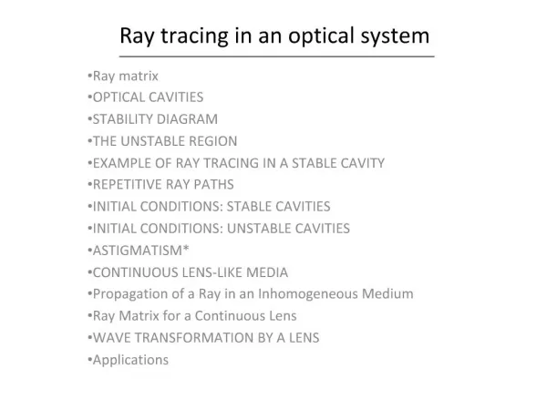
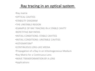
Ray tracing in an optical system Ray matrix OPTICAL CAVITIES STABILITY DIAGRAM THE UNSTABLE REGION EXAMPLE OF RAY TRACING IN A STABLE CAVITY REPETITIVE RAY PATHS INITIAL CONDITIONS: STABLE CAVITIES INITIAL CONDITIONS: UNSTABLE CAVITIES ASTIGMATISM* CONTINUOUS LENS-LIKE MEDIA Propagation of a Ray in an Inhomogeneous Medium Ray Matrix for a Continuous Lens WAVE TRANSFORMATION BY A LENS Applications
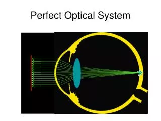
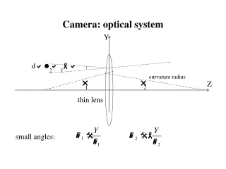
Ray matrix • What we need to describe a ray in an optical system. • 1. Where is it with respect to some arbitrarily chosen axis? • 2. In what direction is it heading? • We start with inspection of the length of free space. • We assume that all rays are paraxial, thus the angle equals the slop of the ray, r’.
write this in matrix form as: • In general, the relation between the output and inputparameters of a general opticalsystem is given by the ABCD matrix of the form: • Thus ray tracing through a sequence of optical components is reduced to simple matrix multiplication. • For instance, if we consider two lengths of freespace.
For optical rays AD — BC =1 is trueprovided that the index of refraction at the exit plane is the same as the entrance plane. Thin lens of focal length f • Here we assume that the lens is so thin that there is negligible distance betweenthe entrance plane 1) and exit plane 2). • Thus no matter what the slope of the incomingray, the output position is always equal to the input position, or Therefore, A = 1 and B = 0.
Now consider the circumstances provided by ray α in the diagram. • For this specialcase the input slope , yet it is obvious that the output slope is In the other case, ray βcomes in with a slope of and obviously exits parallel to theaxis. Thus, r'2 = 0. Therefore ,D = 1
Hence the ray matrix of a thin lens is given by: Combination of a lens plusfree space.
spherical mirror • The entrance and exit planes are on the same side of the surface of the mirror. the effect of the spherical mirror ofradius R is to direct the ray toward the axis just like a thin lens. the focal length of a spherical mirror is just one-half of the radius of curvature. Thus thetransmission matrix is given by:
APPLICATIONS OF RAY TRACING: OPTICALCAVITIES • If the ray position stays "close" to the optical axis , the system is stable; • if the ray naturally "walks off' one of the mirror surfaces,it is unstable; • if the mirrors must be perfectly aligned, itis conditionally stable. equivalent lens-waveguide
Transmissionmatrix for a unit cell Given the information of preceding sections, it is easy to compute the transmissionmatrix of the unit cell shown; it is just the product of two matrices of the form given by:
second-order difference equation for the ray • Let us find a second-order difference equation for the ray as it passes the various • planes of the succeeding unit cells that correspond to observing a ray as it makes successiveround-trips through the cavity. We do this by eliminating the slope from these equations:
Does the equation have solutions in which the magnitude of r is lessthan some maximum value? • It is important to realize why we should ask thequestion. • If the answer to it is yes, thenthe position of the ray form the axis undulates as it propagates along the lens waveguide (orbetween the two mirrors). • If the ray's position is not bounded, it will eventually become sobig that it will "miss" one of the components and thus walk off the mirror.
the position r must be real. • Now r0 is specified by the initial conditions. It cannot be set equal to zero for the generalcase. The exponential term is not zero; hence, the second factor must be zero. That is aquadratic equation in exp(jθ). The two solutions are:
Stability diagram • We can tell by a glance at this graph whether the system is stable or not, if the g parameters is inside the cross-hatched region, the cavity isstable; if outside, it is unstable; and if on the border, it is conditionally stable, requiringperfect alignment. • One of the surprises that this diagram provides is that the confocal geometry, consistingof two identical mirrors and separated by the sum of the two focal lengths, is on the borderlineof stability (g1 = g2 = 0). • Nevertheless,it is on that borderline, and most lasers are made to avoid that situation by increasing ordecreasing d slightly.
THE UNSTABLE REGION resonators operating in the unstableregion have become very useful for high-gain laser systems. In that case, the rays that walk off the mirrors constitute the output. • A very crude example. • After 10 reflections thisbeam missed one of the mirrors. • the medium inside the cavity increasesthe power by a factor of 5. • the emerging beam that misses a mirror is amplified 10 times . • If theinitial beam contained only 1 mW of power, then the emerging beam has nearly 10 kWof power. • Although the example is crude, it illustrates that unstable resonators have theirplace.
EXAMPLE OF RAY TRACING IN A STABLE CAVITY • The incoming ray is perpendicular to the flat mirror) R1= oo) anddisplaced from the axis by a specified amount — r0. Thus this ray is directed toward thefocal point of M2, reflects from the flat mirror, and heads toward the spherical mirror alonga radius. Once this ray reaches M2, it starts a retrace of its initial path and forevermore staysalong paths indicated. This is an example of a repetitive ray path.
The beam stays within a maximum displacement of 2r0from the axis, consistent with the ideas of stability developed earlier.
Why the maximum displacement is r0, where as the simple walk through the cavity indicated that the maximum displacement was 2ro. Why is there a difference? • The ABCD matrix for a unit cell relates the position and slope of the ray as it enters • and leaves the reference planes. It tells us nothing about what happens in between. • If weneed to know about the position between the reference planes of the unit cell (spherical mirror), we must apply the individual ray matrix to obtain that information.
the ray is impinging on the spherical mirror at After one round trip, p = 1, At the end of the second round trip, p = 2, • Note that this last choice of the unit cell tells us nothing about the trials and tribulations ofthe ray at the flat mirror.
REPETITIVE RAY PATHS The preceding example illustrates a case whereby the beam retraces its path after a discretenumber of round trips. In the particular case shown, the ray went three complete round tripsand then was in the same position, with the same slope, as itwas when it started. We cangeneralize this result for any cavity. • If s is increased by m units, corresponding to m round trips, then the ray returns to itsoriginal position after these m round trips, when θ satisfies: • Note that inequality guarantees that θ is always less than π, • in accordance with theprincipal value of cos θ = (A + D)/2.
INITIAL CONDITIONS: STABLE CAVITIES • Let us suppose that we have unfolded a complexcavity and have found the transmission matrix for a unit cell, and that the ray's position aand the slope m are known at a given reference plane (call its = 0). • If a cavity is stable, we can find the angle θ from the transmission matrix of the unitcell: • After traversing • one unit cell • (or round trip):
INITIAL CONDITIONS: UNSTABLE CAVITIES Thus there are two solutions (again), but now they are both real: The general solution becomes: After one round trip.
ASTIGMATISM* • When a material body is placed in the path of a ray and is tilted we must account for the change in the optical path in two orthogonal directions. • Astigmatism of a window, (a) Side view, (b) Top view. • For instance, windows placed at the Brewster angle are very common in gas lasers. The angles θx and θy paraxial to the optic axis. • However, if the dielectric material is a Brewster's angle window on a gas laser tube, then , and for quartz with n = 1.45845,1' 8 = 55.56°. • Obviously, the angle θ-θx is not small, and we must account for bending and resulting displacement of the beam in the xz plane .
It is left as a problem to show that optical paths traversed by the two rays through a Brewster's angle window are different. • The fact that these distances are not equal gives rise to astigmatism. • Refraction angle - α • For example :A curved mirror used in ring laser cavities . The mirror focuses parallel rays in the two planes at different locations, leading to different effective focal lengths in the xy and xz planes. • Astigmatism leads to elliptical beams in ring lasers and plays a critical role in dye-laser cavities.
CONTINUOUS LENS-LIKE MEDIA • a medium in which the index of refractionis nonuniform in the transverse direction. • Optical fiber with an index of refraction depending on r.
Variation of the index of refraction of a gas due to local heating by thecurrent density distributed as in (b).
Propagation of a Ray in anInhomogeneousMedium • propagation of aray in an • inhomogeneous dielectric medium.
Ray Matrix for a Continuous Lens A simple thin positive lens • more mass and a longer optical paththere than at the edges. • Similarly, a positive continuous lens has an index of refraction thatdecreases with r. • For a cylindricallly symmetric positive lens, the first two terms of Taylorseries expansion for n(r) would have the following format: • the parameter Lis simply a scalefactor that indicates how fast n varies with r. • For instance, if a = 50 μm for the radius ofthe fiber and n(a) = 1.42 with n0 = 1.47, then Δn = 0.05. The relationshipbetween Δn and L is given by simple arithmetic:
Because of the inequality we can use the first term for n andthe derivative of the second for dn/dr: • For the numbers just quoted, I = 191.7 μm which is large when compared with theradiusof the fiber. Most fibers have a change in index much less than the value chosen here, andhence L is even larger. • The solution is straightforward. Assume that z= 0 is the input plane to this opticalcomponent where the position r and slope r' areknown: • Then, by differentiation, we obtain the slope at any position z:
Thusthe ray matrix for a length z = d is: then the medium is uniform • If the index of refraction increases with r (as in the case of a gas discharge), then the • geometric factor L must take on imaginary values to predict n(r) from the equation: • If welet L = jL and use the fact that cos iθ = cosh θ, sin iθ = i sinh θ, • we obtain the raymatrix for a negative lens directly from the T matrix:
The C term in this matrix is the negative of the focal length of thislens: • Thus the focal length is positive (i.e., converging) provided that the argument of • the sinefunction is less than π radians. • If d is long enough )as in a fiber-optic communicationsystem (the focal length is alternately positive and negative, corresponding to a convergingand diverging system. • Thus we could anticipate the "beam" undulating as shown in the Figas it propagates down the fiber. • Going one step further, anticipate a situation wherethe natural divergence of a small beam is continuously counteracted by the convergence ofthe medium. • Such fibers exist and are used in fiber-optic communication links.
WAVE TRANSFORMATION BY A LENS • The effect of a lens on a limited extentuniform plane wave. • What is the shape of the phase front • afterpassing through the lens? • The Fermat principle;the light always takes the path that makes the transit time a minimum. • The rayat B' has farther to travel; hence, its phase must be ahead of that ofA'. • This extra distanceisΔd.
Applications • In computer graphics, ray tracing is a technique for generating an image by tracing the path of light through pixels in an image plane and simulating the effects of its encounters with virtual objects. • The technique is capable of producing a very high degree of visual realism, but at a greater computational cost. • Ray tracing is capable of simulating a wide variety of optical effects, such as reflection and refraction, scattering, and chromatic aberration.