Download
1 / 1
10 likes | 122 Views
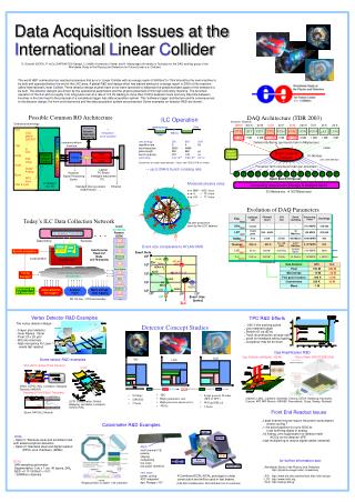
receiver. receiver. receiver. Buffer. Buffer. Buffer. FPGA. FPGA. FPGA. ILC Operation. 5 Hz. 2820 bunches. /. //. /. DAQ Architecture (TDR 2003). 199 ms. 1ms. Detector Channels. 799 M. 300 K. 40 M. 1.5 M. 20 K. 32 M. 200 K. 75 K. 40 K. 20 K. VTX. SIT. FDT. TPC. FCH.

E N D
receiver receiver receiver Buffer Buffer Buffer FPGA FPGA FPGA ILC Operation 5 Hz 2820 bunches / // / DAQ Architecture (TDR 2003) 199 ms 1ms Detector Channels 799 M 300 K 40 M 1.5 M 20 K 32 M 200 K 75 K 40 K 20 K VTX SIT FDT TPC FCH LAT ECAL HCAL MUON LCAL cms energy500800GeV repetitionrate 5 4 Hz bunches/pulse 2820 4886 pulse length 950 860 μs bunch spacing 337 176 ns luminosity 3.4x1034 5.8x1034 cm-2s-1 (Parameters are under reconsideration. Values from TESLA TDR are shown) Possible Common RO Architecture 20 MB 1 MB 2 MB 110 MB 1 MB 90 MB 3 MB 1 MB 1 MB 1 MB Detectors technology Detector Buffering (per bunch train in Mbytes/sec) Services Synchro Calibration Monitoring Links VTX CCD MAPS DEPFET ….. TRK Si TPC ECAL SiW Other HCAL Digital Analog Muon RPC Scint VFD & Lumi ….. ? Integration to be studied! Event manager & Control Event building Network 10 Gbit/sec L O C A L B U F F E R → up to 20kHz bunch crossing rate (LHC CMS 500 Gb/s) common/uniform Interface NETWORK Processor farm (one bunch train per processor) FPGA local data collection node Preamp. Shaper Digitizer P P P P P P P P P P P P P P P P Select Bunch Of Interest Moderate physics rates e+e- WW → 930 / hour e+e- tt → 70 / hour e+e- HX → 17 / hour top pair production seen by the LDC detector Computing ressources (Storage & analysis farm) Laptop PC Board Intelligent mezzanine PC… Receiver Signal Processing Buffer 30 Mbytes/sec 300TBytes/year on detector very FE Standard links & protocol USB,Firewire ….. Ethernet Today’s ILC Data Collection Network Evolution of DAQ Parameters Local/ worldwide Remote (GDN) Channel count L1A rate Event building Processing. Power Sociology Exp. Collision rate On detector Front End Year UA’s 3 µsec - - - 5-10 MIPS 150-200 Data link(s) Services 1980 LEP 10-20 µsec 250 - 500K - 10 Mbit/sec 100 MIPS 300-500 Run Control 1989 receiver Event size comparable to ATLAS/CMS Buffer Sub Detector Read-Out Node (COTS boards) BaBar 4 ns 150K 2 KHz 400 Mbit/s 1000 MIPS 400 Event Rate FPGA Synchronisation Proc 1999 106 Tevatron 396 ns ~ 800 K 10 - 50 KHz 4-10 Gbit/sec 5.104 MIPS 500 Monitoring Histograms LHCb Local partition 2002 ATLAS CMS Networking Hub Ktev Btev LHC 25 ns 200 M* 100 KHz 20-500 Gbit/s >106 MIPS 2000 105 HERA-B 2007 ILC 330 ns 900 M* 3 KHz 10 Gbit/s ~105 MIPS > 2000 ? Event Display KLOE CDF/DO II 104 2015 ? Local/GlobalNetwork(s) Wordlwide! Config Manager * including pixels Sub-Detector LHC ILC CDF DCS 103 H1ZEUS Pixel 150 M 800 M ALICE Microstrips ~ 10 M ~30 M NA49 UA1 102 Machine Bx BT feedback Databases Data collection Sw triggers Analysis Farm Mass storage Data logging Fine grain trackers ~ 400 K 1,5 M 104 105 106 107 Calorimeters 200 K 30 M LEP Event Size (bytes) ... Muon ~1 M NO On line – Off line boundary ILC TPC R&D Efforts Detector Concept Studies • ~200 3-dim tracking points • Low material budget • Particle ID via dE/dx • Track reconstruction at large radii • avoid Ion feedback without gating • occupancy may be an issue GLD Gas Amplification R&D SiD LDC Iron Yoke Gas Electron Multiplier (GEM) Micro Mesh (MICROMEGAS) • TPC • High granularity calo • High precision microvertex • 4Tesla • Large gaseous Tracker (JET or TPC) • W/Scint EM cal • 3 Tesla • Si Strips • SiW EM • 5 Tesla Vertex Detector R&D Examples Main Tracker EM Calorimeter (Aachen, LBNL, Carleton, Montreal, Victoria, DESY, Hamburg, Karlsruhe, Cracow, MIT, MPI Munich, NIKHEF, Novosibirsk, Orsay, Saclay, Rostock) The vertex detector design : • 5 layer pixel detector • Inner Radius: 15mm • Pixel: 20 x 20 μm2 • 800 mio channels • High occupancy for Layer 1 needs fast readout Had Calorimeter Cryostat/Coil VME/… VME/… Some sensor R&D examples HCAL HCAL Monolithic Active Pixel Sensors CCD ASIC multi channel (18) preamp shaping multiplexing low noise low power (5mW/ch) next steps : power cycling ADC integrated dyn. Range >104 BEAM BEAM ECAL ECAL Beam Beam (IReS, LEPSI, RAL, Liverpool, Glasgow, Geneva, NIKHEF) monitoring monitoring Movable table Movable table Depleted Field Effect Transistor A Combined ECAL/HCAL prototype is under construction and will be used in test beams. (LCFI Collaboration: Bristol, Glasgow, Lancaster, Liverpool, Oxford, RAL) Readout ASIC on wafer 1-2k channels (CALICE Collaboration: 26 Institutes from 9 countries) (Bonn, MPI HLL Munich) Data Acquisition Issues at the International Linear Collider G. Eckerlin (DESY), P. le Du (DAPNIA CEA Saclay), U. Mallik (University of Iowa) and H. Matsunaga (University of Tsukuba) for the DAQ working group of the Worldwide Study of the Physics and Detectors for Future Linear e+e- Colliders The world HEP community has reached consensus that an e+e- Linear Collider with an energy reach of 500GeV to 1TeV should be the next machine to be built and operated before the end of the LHC area. A global R&D and design effort has started aiming for a design report in 2006 of this machine called International Linear Collider. Three detector design studies have so far been launched to elaborate the possible phase space of the detectors to be built. The detector designs are driven by the operational parameters and the physics potentials of this high luminosity machine. The bunched operation of the ILC with a roughly 1ms long pulse train at a rate of 3-5 Hz leading to more than 100ms between trains and very little time between bunches in the train lead to the proposal of a completely trigger less data acquisition system. This 'software trigger' architecture and its consequences to the detector design, the front end electronics and the data acquisition system are presented. Some examples on detector R&D are shown. Front End Readout Issues • Large channel counts require low power consumption power cycling ? • 1 ms active pipeline for up to 5000 bx local buffering digital or analog • hit finding, zero suppression on detector itself ACICs on the detector VFE • high multiplexing to reduce signal cables (material) Calorimeter R&D Examples HCAL • Option I: Stainless steel and scintillator tiles with advanced photo detectors • Option II: Stainless steel and digital readout (RPCs, wire chambers, GEMs) for further information see: • Worldwide Study of the Physics and Detectors http://physics.uoregon.edu/~lc/wwstudy • SiD http://www-sid.slac.stanford.edu http://sid.fnal.gov • LDC http://www.ilcldc.org • GLD http://ilcphys.kek.jp ECAL SiW sampling calorimeter Segmentation: 1cm x 1 cm, 40 layers, 24X0 ΔE/E =0.11/√E(GeV) + 0.01 ~30Milllion channels