
CSSE374 – Course Intro
Right: Architecture in Tunisia – It’s always good to ask the client what they want. It might not look like what you’d expected. CSSE374 – Course Intro Steve Chenoweth Day 1, Dec 1, 2008 Today What’s in the course & why Arch & design - How do you know if you succeed?

CSSE374 – Course Intro
E N D
Presentation Transcript
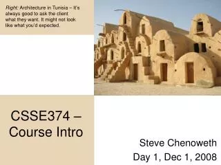
Right: Architecture in Tunisia – It’s always good to ask the client what they want. It might not look like what you’d expected. CSSE374 – Course Intro Steve Chenoweth Day 1, Dec 1, 2008
Today • What’s in the course & why • Arch & design - How do you know if you succeed? • Let’s start with some bridges • And some basic principles • And an intro to the book
What’s in the course & why • Let’s look at course web site (on AFS): • Policies • Schedule, with links to everything that will exist • Ideas for projects – from past classes • Discuss how the projects will work: • Teams of 2 – How formed? • By 6 AM Thurs: On Angel Wiki Survey, identify a team-mate. • If you’d like to be the one team of 3, let me know. • Acting as clients, architects, and implementers • On 3 different projects
Lessons from five bridgesWhat are “Success and Failure”? • Split into five groups in class • Each group looks at one bridge, and list answers to these questions: • In what way(s) was this bridge a success? (or might it be a success) • In what way(s) was this bridge a failure? (or might it be a failure) • How could better requirements (versus design) have made a difference? • How do you imagine the lessons here could apply to software development? • This Should Take About 15 Minutes: 5 Minutes to read 5 Minutes - Groups discuss their bridge 5 Minutes: A quick class readout from all the groups
The Britannia Tubular BridgeMenai Strait, UK: 1850-1970 The Britannia Tubular Bridge was a civil engineering project in the late 1840s, and opened in 1850, to complete a section of the British railway system. The bridge is 1500 feet long, in four sections: There are two approaches of about 250 feet each, and two center spans of 500 feet. These four spans were built of rectangular, wrought-iron tubes, connected together to form a single, 1500-foot-long tube through which the trains passed. Because of intense competition in the railroad business, completion time was of extreme importance to the railroad company. Therefore the project was “fast-tracked,” with construction underway before all details of the design were worked out. Most visibly we have the tall towers—at the time construction started, it was not known for sure whether the tubes themselves would be sufficient to carry the trains, or whether additional support would be needed. The towers were intended to support suspension chains if these were needed. Calculations during construction showed they weren’t, so the towers remain superfluously tall. Total cost of the Britannia Bridge was £600,000, very high in 1840s money. About 75% of this was spent on the construction and raising of the tubes, which weighed some 1,500 tons each (7,000 pounds per foot of railway track). The bridge was used from its opening until 1970, when a fire (in a wooden roof built to protect the iron tubes from rain) damaged it beyond repair. The folklore is that the fire was set accidentally by kids using torches to look for bats in the tunnel. The Britannia Bridge was a celebrated engineering feat at the time; however, only a few other tubular railway bridges were built. Truss-and-girder bridges requiring on the order of 5,000 pounds of iron per foot of track were under construction by 1860, and suspension bridges requiring less than 3,000 pounds/foot were in use by 1870. In addition, passengers found the experience of passing through the tubes (where temperatures could reach 110 degrees on a summer day) in trains pulled by coal-fired locomotives to be quite unpleasant. The Britannia Bridge may be viewed as the ancestor of the many box-girder bridges built since the 1940s, although the tubular girders of these bridges are welded rather than riveted, traffic rides on top of the tube rather than inside it. Source: Henry Petroski, Design Paradigms A painting of the Britannia Bridge, showing how the tubes form a 1500-foot iron tunnel, 100 feet above the water.
The Niagara Gorge Suspension BridgeNew York, USA: 1855-1897 The Niagara Gorge Suspension Bridge, was designed by John Roebling (who would later be known for the Brooklyn Bridge). The bridge was definitive proof that suspension bridges could carry rail traffic. Before that time, most bridge designers, particularly those in Britain, had maintained that suspension bridges were unsuitable for rail traffic, despite their ability to span longer distances with much less material than truss-and-girder designs. For railroads, the problem with using suspension bridges was that the concentrated load of the locomotive(s) would cause the bridge to deflect. This created a “low spot.” If the bridge deflected far enough, the low spot would be so low that the train couldn’t climb back up. (Very embarrassing for the designers!) Additionally, suspension bridges had gotten something of a reputation for being blown down by strong winds—for instance, the Menai Straits bridge in England (a road bridge near the Britannia Bridge) had been severely damaged by wind on several occasions. Roebling solved the problems of carrying rail traffic by stiffening the bridge deck with a deep wooden truss, and tying the deck in place with a series of cables, both above (to the towers) and below (to points on the gorge wall). When the Niagara Bridge opened in 1855, it was at 820 feet nearly twice the length of the longest single railway span built to date, and used barely half the material per foot of track, compared to other designs. Roebling wrote an engineering report on the bridge, systematically examining the forces that could cause a suspension bridge to fail, and describing in detail the provisions his design made for stiffness and stability. The main point of this report, of course, was to prove that his design idea was the best choice for the job. While Roebling understood and dealt with the physical forces that could make suspension bridges unsuitable for trains, he had not anticipated the growth of railroad trains. Trains in general, and locomotives in particular, grew much heavier in the 40 years after the Niagara Gorge bridge was built, leading to its replacement by an arch bridge in 1897. By this time Roebling had designed and built many longer suspension bridges, including the Brooklyn Bridge, and suspension was well-established as the approach of choice for long bridges in North America. Source: Henry Petroski, Design Paradigms An illustration of the Niagara Gorge Bridge. Visible are the diagonal stays above and below the bridge deck, the deep truss (with trains running above and carriages below), and the relatively small train by today’s standards.
The Tacoma Narrows BridgeWashington State, USA—1940 The Tacoma Narrows bridge is possibly the most famous bridge in the world, having had the great misfortune of collapsing in front of the movie camera. Millions of physics students have watched the bridge’s twisting as an example of harmonic motion. The collapse movie is even included as a part of the definition of “Bridge” in the Microsoft Bookshelf CD-ROM package! The bridge was opened in 1940 to connect the city of Tacoma with the navy yards on the other side of the Narrows. It was designed by Leon Mosseiff, a highly-respected engineer who had worked earlier on the George Washington and Bronx-Whitestone bridges in New York and was one of the designers of the Golden Gate bridge. Mosseiff had developed the “modified deflection theory,” which held that the weight of a bridge deck could resist wind pressure without the need for additional trussing or stays; hence Mosseiff favored an aesthetically-pleasing slender deck braced only by 8-foot tall plate girders. Some engineers had been concerned about the extreme length-to-width ratio of the Tacoma Narrows bridge, but Mosseiff’s calculations and reputation overcame any objections. From the day it opened, the bridge moved in the wind, much more than expected, and gained the nickname “Galloping Gertie.” Often the movement took the form of an increasing oscillation, and the bridge became the object of study to determine why it moved. Therefore, when it started moving in a fairly light (40 mph) wind on November 7, 1940, the cameras were ready. This time the oscillations built until cables snapped and a substantial section of the roadway fell. Because of ample warning, there were no human injuries. The bridge was completely destroyed; even the towers were bent to the point where they had to be torn down and rebuilt. Post-collapse analysis, including wind-tunnel testing of models, showed that the flexible bridge deck was flapping like a flag in the wind—the flexing of the bridge changed how it responded to wind, creating a positive feedback loop. Mosseiff’s theory had dealt only with static wind loading and ignored dynamic effects. It was not until the late 1940s that David Steinman (a member of the team investigating the collapse) felt this problem of aerodynamic movement in suspension bridges was solved; he and applied his findings to the Macinac Bridge in Michigan. Meanwhile, the Tacoma Narrows Bridge was rebuilt, with a more traditional deep truss stiffening its roadway. The replacement bridge has stayed put in much higher winds and is in use today. Indeed, as of this writing, a second, similar bridge is planned to be built next to it, to handle increased automobile traffic across the strait. Source: Petroski, Design Paradigms; Levy & Salvadori, Why Buildings Fall Down “Galloping Gertie” crosses the finish line.
The Humber BridgeHumberside County, UK: 1981- From its completion in 1981 until the opening of the Akashi-Kaikyo Bridge in Japan, the Humber Bridge was the longest suspension bridge in the world. It also holds the distinction of being the first major suspension bridge to use concrete towers. Its deck, rather than having a deep truss to resist wind movements, is in the form of an inverted wing, so that the bridge actually becomes “heavier” and more stable in wind. However, the bridge also boasts one of the most rapidly increasing debts of any public project, with no real long-term hope of ever paying off the loans taken to build it. The idea of building a road bridge across the Humber Estuary first came up in 1959, as a project to assist local development by increasing mobility and promoting industrial growth. Actual design and construction began in 1971, with an estimated cost of £23 million and a planned opening in 1976. As usual, the financial viability of the bridge relied on a certain, perhaps optimistic, timetable for the project. The construction project ran into serious problems in the foundations for the south support tower. The geology was risky—the foundations went into “Kimmeridge clay,” which is highly sensitive to water content: if it gets too dry, it crumbles; if it gets too wet, it turns to mud. Since the south tower is located in the river, this is a tough problem. It got worse when the half-sunk caisson encountered artesian water. The caisson had to be modified in place, and the remaining excavation and sinking was done underwater by divers. As a result the foundations for the south tower were not completed until 1976—the original planned opening date for the bridge. Meanwhile, there was a steel strike, inflation, recession, and soaring interest rates for the project to contend with. These all took their toll in time and money, so that when the bridge finally opened in 1981 (five years late) it had cost £91 million, with another £54 million in interest already accrued, for a total opening-day debt of £145 million. Once the bridge was open, the planned traffic flow failed to materialize. Industrial development in the region was stagnant, and in the words of one local commentator, “nobody in particular wants to travel between Grimsby and Hull.” Traffic on the bridge has never been anywhere near enough to cover interest, so the debt continues to increase. If current trends continue, the debt will rise to the billions and then trillions of pounds by 2043, the date the bridge would be, under its original plans, paid for. The engineers involved in building the bridge apparently suspected the traffic foreccasts were unlikely to be achieved. However, once construction had been started, they had to consider the benefit of local jobs in doing that, and also the reaction they’d get from political and community leaders who had sponsored the bridge. Sources: Bignell & Fortune, Understanding Systems Failures;Hawkes, Structures The Humber Bridge during a typical rush hour. What’s missing in this picture?
Strait of Messina Bridge Project (Once due to start construction in 2004, then cancelled by new Italian government in 2006. In the end, who knows?) would have to be huge to cause trouble, as the bridge could face without damage a seismic action corresponding to 7.1 magnitude in Richter scale (severer than the earthquake that destroyed Messina in 1908). Construction had been slated to start in 2004, then 2006 with completion in 2012. The only obstacle left was funding. The bridge was expected to cost five billion dollars. The bridge would be 60 m (196 feet wide) and have 12 lanes for traffic and two lanes in the middle for trains. This would allow 140,000 vehicles and 200 trains per day. This would cut down transit times of up to 12 hours (via ferry) down to minutes. Ever since Giuseppe Garibaldi landed in Sicily in 1860, completing the unification of the nation, Italians have considered building a bridge over the Strait of Messina, so this bridge is tied to long-held political aspirations. Sicily and the neighboring mainland area of Calabria are among the poorest regions of Italy. Analysts say the bridge would boost the economy there, attracting tourism. However, critics pointed to the environmental impacts of the bridge and its construction, and also to the fact that many other, less glamorous infrastructure projects were desperately needed. And there was a crack in the bridge’s role in national unity, in that opponents suggest the construction project was a “banquet for organised crime.” In 2006 two ministers of the newly elected government of Romano Prodi stated their opposition to the project when taking up office. In August 2006, the project was announced as "under review" for budgetary reasons. Citing concerns that the project was too expensive, was likely to enrich criminal gangs, and might not be earthquake-proof after all, the project was terminated in October 2006, over protests from southern Italian legislators. Provided by Stretto di Messina S.p.A. and news sources. This project if completed would be one of the Landmark Bridges of the 21st century, the longest span suspension bridge ever built (between towers). The Strait of Messina divides the island of Sicily from Calabria in southern Italy, and is 2 miles (3km) wide. The overall length is not a big problem, per se, but water depth, wind, and earthquakes all must be considered. After 50 years of study, the bridge looked possible if maybe not economical. To avoid the problem of the deep water, the solution was to design the longest suspension bridge ever. It would have a 3300 m (2 mi) main span and 180 m (590 ft) side spans (overall length 3.7 km(2.5 mi)). The main piers would be founded in 120 m (400 ft) of water. There was to be a new patented lighter deck design which dealt with aerodynamic and seismic problems. The wind would be no problem as the aerodynamic features of the bridge would allow it to withstand 216 km/hr (134 mi/hr). Earthquakes
Some basic principles • Architecture / design is about a project • Know who defines success & failure • Results – doing right things right • Understanding the problem and the solution • Knowing how to get from one to the other
Architecture / design is about a project • What’s a project? • A sequence of unique, complex, and connected activities having one goal or purpose and that must be completed by a specified time, within budget, and according to a specification*. -- From Effective Project Management: Traditional, Adaptive, Extreme, by Robert K. Wysocki, p. 4. (This year’s book for CSSE 372). *For architecture, the meaning here is: specification = requirements. For lower-level design it could mean more. Why?
Who defines “success and failure” of the project? -- Key project players • The dilemma: • Many key players • You’d like to satisfy them all, but their needs and wants are In conflict • Your business needs to make money now and in the future Customer Reps** End Users The Impacted+ Developers Related Proj. Testers Process Owners* Some filter about what to do The System *Like project managers. +Perhaps spoken for by regulators, etc. **Often via your marketing people.
Who defines “success and failure” of the project? -- Key project players • A solution: Identify your client • The client controls the money that pays for the system • This sets the priorities on the needs/wants of all stakeholders • The architect/designer’s job is to assist the client in making the decisions that will lead to a successful system. Why? Customer Reps** End Users The Impacted+ Developers Related Proj. Testers Process Owners* Client (Vision & $) The System *Like project managers. +Perhaps spoken for by regulators, etc. **Often via your marketing people.
“Doing the right thing right” Successful architecture addresses two questions: • Does the system as built accurately implement what the specification described? (Does it do the thing right?) • Does the specification accurately describe what the important people wanted? (Does it do the right thing?)
“Doing the right thing right” And we can measure the answers to both of these: • Does it do the thing right? • Associated with “Quality” and with verification of the project (black box and white box testing vs specs). • Does it do the right thing? • Associated with requirements, validation of the project and black-box “acceptance” testing in the project
“Doing the right thing right” • What was missing from each of the bridges? • Does the definition of “success and failure” depend on where we draw the boundary around the project?
Problems and solutions Architects must know high-level problems and solutions: • Problem: A difference between what a person sees and would like to see • Solution: A plan for bringing reality as seen and reality as desired into agreement In lower-level designs, we merge the high level solution ideas with lower-level requirements, extending that design. Which isn’t always smooth…
Problems and solutions Architecture especially involves both problems and solutions: • To the architect, a concise problemstatement or “needs” statement is crucial: It drives high-level design decisions • A few paragraphs to a couple pages, defining the center and the boundary of the product scope, and leaving room for innovative solutions • This is a big reason why we insist on problem statements
Vague Idea of Problem How do you get to the solution? In an ideal world (and often in the client’s head): Perfect Understanding of Problem Perfect Blueprint for Solution ...in a single bound!! In this world, some number of “rough sketches” are needed: First Tries at Solution Better Idea of Problem “Good Enough” Blueprint for Solution Better Ideas of Solution “Good Enough” Idea of Problem • • • (First Architecture) (First Problem Statement) (Final Detailed Design) (Final Requirements) Note that each step may involve multiple “rough sketch” solutions And of course at the same time the client is cycling, and getting a better & better idea of what they really wanted…
What do designers do? • Half technical • Half social • Like explaining what the design means • Like talking people into doing things • Architects have to talk to “outsiders,” too “Ok, here we are. What are we supposed to do?”
Larman’s text • Widely used in OO Design courses and OO software engg courses • You’ll need a copy • Tonight – read Ch 1-3 – the intro, including case studies • Tomorrow we’ll also discuss Inception • Here’s what’s in the book:
Larman’s text, cntd • Part I – Introduction • Part 2 – Inception • Part 3 – Elaboration iteration 1 – Basics • Part 4 – Elaboration iteration 2 – More patterns • Part 5 – Elaboration iteration 3 – Intermediate topics • Part 6 – Special topics
Larman’s text, cntd • Part I – Introduction • Explains the iterative approach he’ll take • Introduces his two case studies • Part 2 – Inception • How to start an interative/agile project • The big picture • Review of use cases & other requirements
Larman’s text, cntd • Part I – Introduction • Part 2 – Inception • Part 3 – Elaboration iteration 1 – Basics • Part 4 – Elaboration iteration 2 – More patterns • Part 5 – Elaboration iteration 3 – Intermediate topics • Part 6 – Special topics