Download
1 / 29
290 likes | 498 Views
Design and Evaluation of a Twisted Savonius Wind Turbine. Ian Duffett Jeff Perry Blaine Stockwood Jeremy Wiseman. Outline. Problem Definition Introduction Concept Selection Design Fabrication Testing Results Conclusions Recommendations. Problem Definition.

E N D
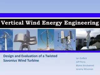
Design and Evaluation of a Twisted Savonius Wind Turbine • Ian Duffett • Jeff Perry • Blaine Stockwood • Jeremy Wiseman
Outline • Problem Definition • Introduction • Concept Selection • Design • Fabrication • Testing • Results • Conclusions • Recommendations
Problem Definition Design and test a vertical axis wind turbine (VAWT). This design should meet the following objectives: • Design will be novel and untested • Design will be self-starting • Design will produce reliable power in harsh weather conditions
Wind Energy • The conversion of wind energy into various other useful forms such as electricity is known as wind power • Studying wind energy is desirable because: • Wind energy is renewable • There is ample supply of wind energy • Suitable wind patterns are available worldwide • Production costs of wind energy are declining • Wind energy produces minimal greenhouse gas emissions
Wind Turbines Horizontal Axis Wind Turbines (HAWT) Vertical Axis Wind Turbines (VAWT) Advantages Ground mounting makes maintenance easier Can be installed in areas of wind funnelling and high wind speeds Lower noise signature Requires lower starting speeds Disadvantages Lower efficiency May require guys to support rotation axis Can create an inconsistent torque (pulse) Advantages • Higher efficiency • Can furl out of the wind to reduce wind speed seen by the blades • High towers reduce turbulence caused by nearby structures Disadvantages • Tower mounting makes maintenance more difficult • Requires large structures • Installation requires heavy equipment • Requires additional controls to furl and rotate to orient blades in the wind direction
Major Types of VAWT • Darrieus Wind Turbine • Uses lift to create rotation • Good efficiency • Torque ripple • Not self-starting • Savonius Wind Turbine • Uses drag forces to create rotation • Low efficiency • High reliability • Self-starting A very large Darrieus wind turbine on the Gaspé peninsula, Quebec, Canada Savonius wind turbine
Twisted Savonius • Increases efficiency of standard savonius wind turbine • Consistent torque created by symmetrical helical shape • Rotates regardless of wind direction • Self-starting
Concept Selection Modified Twisted Savonius Turbine • Provides consistent torque • Will be self-starting • Will only rotate at the wind speed allowing for greater reliability in high wind • Design is untested • Closed around shaft
Prototype Modelling Bottom Plane Bottom Plane Independent Design Parameters: • Long Radius • Short Radius • Angle of Twist α Short Radius r Short Radius r Top Plane R Long Radius Bottom Plane R Long Radius α Top Plane 360 ° 180 ° 360 ° 180 °
CFD Analysis • FloWorks simulation developed to test static torque on various foil designs: • Constant velocity air stream, 15m/s • Measure torque generated on shaft
CFD Analysis Circular Foil Design • Maximum Torque @ 360° Twist Angle 0.47 N·m Elliptical Foil Design • Maximum Torque @ 360° Twist Angle, 108.3 mm Long Radius 0.56 N·m
Prototype Fabrication Rapid Prototyping • Fused Deposition Modeling • Turns computer-aided design (CAD) geometry into solid state structures. • Max Build Size 10” x 10” • Sectioned Prototype • Required Build time ~ 36 hours per section • Two Section Shaft • $6300
Prototype Fabrication • Design Plan
Prototype Fabrication • Prototyping Challenges • Prototyper Size Constraints • Problem: Limitations in nozzle movement prevented achieving maximum cross-section • Solution: 5% Reduction in CAD Model Size • Problem: Damage to nozzle heads due to overheating of material in the semi-liquid state • Solution: Reduced size (by height) of individual foil sections to decrease run time and prevent overheating
Prototype Fabrication • Prototyping Challenges • Assembly • Problem: Shrinkage of the material during cooling from the semi-liquid state • Solution: Use of body filler during assemblage to create continuous foil surface • Problem: Rotational unbalance within the foil due to body filler and flexibility of shaft • Solution: Replacement of two shaft aluminum design with single steel shaft
Wind Tunnel Setup • Memorial University’s Wind Tunnel • - Wind Speed Range • 1.2 m/s (Full Closed) to 10.6 m/s (Fully Open) • - Rectangular test section • 20.0 x 0.93 x 1.04 meters
Wind Tunnel Setup • Setup 1 • Installed centered and vertically in the wind tunnel with both ends of the shaft extruding through the bottom and top of the tunnel (2 x Alum 1/2” OD x 36”, inserted at both ends) • Low friction polyblockbearings • Setup 1 Problems • Large vibrations during rotation of Blade • Not installed: • Friction Brake Dynamometer • Anemometer • LED Tac
Wind Tunnel Setup • Setup 2 • Installed centered and vertically within the wind tunnel with a shorter shaft (Steel 7/16” OD x 36”) • Low friction shaft bearings • Instrumentation setup: • LED Tac / Handheld Tac • Friction Brake Dynamometer • Anemometer • Setup 2 Problems • Vibration of Friction Brake Dynamometer • Pulse loading on load cell • LED Tac sampling rate limited to 50 Hz • Unable to capture flywheel rotations fast enough
Wind Tunnel Setup • Setup 3 • Installed centered and vertically within the wind tunnel with a shorter shaft (Steel 7/16” OD x 36”) • Low friction shaft bearings • Instrumentation setup: • Handheld Tac • Friction Brake Dynamometer • Anemometer • Setup 3 Problems • Vibration of Friction Brake Dynamometer • Pulse loading on load cell
Testing Matrix - Number of Tests -> 36
Testing Predictions Predicted Results Two important design features are: • Tip Speed Ratio (TSR or ) • Is the ratio between the rotational speed of the tip of a blade and the actual velocity of the wind • Power Coefficient (Cp) • The power coefficient tells how efficiently a turbine converts wind energy into electricity
CFD / Testing Comparison FloWorks simulations were developed over a range of wind speed for static torque and compared to static test acquired throughout testing
Summary • Successful test of novel design • Design determined to be self starting under varying wind conditions • Maximum 15% efficiency achieved • Maximum Power Output of 13 Watts • Cp vs. TSR Plot follows a similar profile of the predicted • Power and torque output increases as wind speed increases
Plan Forward & Next Steps • Improve testing set-up for more reliable results • Use high frequency DAQ to accurately measure rotation speed • Review friction brake design to measure more consistent loads • Test under Newfoundland environmental conditions • Icing and snow tests • Higher wind speeds • Longer term effect of sea spray and fog on system performance
Special Thanks to: • Dr. Iqbal • Steve Steel • Matt Curtis • Craig Mitchell • Don Taylor
This Concludes our Presentation Questions? Thank you for your Attention http://www.engr.mun.ca/~blaines/