N5264A
420 likes | 653 Views
New. N5264A. PNA-X Measurement Receiver Jim Puri Applications Specialist March 2009. N5264A Measurement Receiver. No connectors on front panel. LO out (Opt. 108). USB 2.0. 10/100 Mbps. Five IF inputs (7.605634 MHz). N5264A PNA-X Measurement Receiver. N5264A Description:.

N5264A
E N D
Presentation Transcript
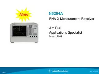
New N5264A PNA-X Measurement Receiver Jim Puri Applications Specialist March 2009
N5264A Measurement Receiver No connectors on front panel
LO out (Opt. 108) USB 2.0 10/100 Mbps Five IF inputs (7.605634 MHz) N5264A PNA-X Measurement Receiver
N5264A Description: • Measurement Receiver for antenna and system level applications. • Five IF inputs are in the rear. • Two hardware configurations: • Receiver only (8530 equivalent) • Receiver with LO source • Key Aspects: • Five IF inputs available (thereby eliminating the PNA-X test set, which is not required for antenna systems) • FIFO (enabling infinite measurement durations). • Point mode (enabling point averaging). • 8530A Drop-in replacement (for equivalent functionality). • Hard-drive removal *** for secure environments *** • Two Software option: • Fast-CW (Circular buffer, FIFO) mode • Time domain (Opt. 010)
Key Specifications: • Data acquisition time (speed) = 400,000 / Sec (Opt. 118 Fast-CW mode) • Input compression point (.1dB)= -10.00 dBm • Sensitivity (noise floor) = -145 dBm (worst case @10Hz IFBW, 0 average) • Dynamic Range = 135 dB (worst case @10Hz IFBW, 0 averages) • Measurement Receiver = 5 with 5 inputs (data taking simultaneously) • Data Buffer = 500,000,000 points • Target Customers: • All 8530A antenna end-users • All antenna system integrators • Key Applications: • Antenna test (A/D and Commercial) • Radome tests • System Integrator (ATE)
N5264A Model Number Structure N5264A PNA-X Measurement Receiver This is the same LO output on the rear of the PNA-X (typical output +10dBm) Opt. 108 Add LO Source .01 - 26.5 GHz Opt. 118 Add Fast-CW (FIFO) mode Opt. 010 Time Domain
Positioner controller Source antenna Meas Ant. 85320A Using 85309A Ref antenna 85320B GPIB Positioner 85309A 8360 series Microwave Source Software 8530A Test Ref. HP 9000 workstation 8360 series Microwave source GPIB GPIB Extender GPIB Extenders 8530A (85301B) Far-Field Configuration End of Support Life April 1st, 2009.
Positioner controller Source antenna Meas Ant. 85320A Using 85309A Ref antenna 85320B GPIB Positioner 85309A New 8360 series Microwave Source Software Test Ref. End of Support Life August 1st, 2009. HP 9000 workstation 8360 series Microwave source GPIB GPIB Extender GPIB Extenders 8530A (85301B) Far-Field Configuration 8530A replaced by the New Antenna Receiver
Source antenna Optionalamplifier 85320ATest mixer AUT PSG or MXG 85320BReference mixer PSG Synthesized source PositionerPowerSupply GPS sync Triggerout LAN LO in 85309A Trigger in Measurementautomationsoftware Positioner controller 7.606 MHz LO out (Opt. 108) LAN Router/Hub 10 MHz in/out LAN LAN PNA trigger out PNA trigger in PNA-X and PSG N5264A opt. 108 8530A (85301B) Far-Field Configuration8530A replaced by the New Antenna Receiver & 8360 source with MXG for faster measurement speed New
8530A versus New PNA- X Measurement Receiver based System Performance Summary( with 85309A, 85320A/B mixers)
End of Support Life April 1st, 2009 8530A based (85301C) System
End of Support Life August 1st, 2009 N5280A N5264A opt. 108 LO In LO Out 8530A based (85301C) system Replacing 8530A with new antenna receiver opt. 108 and 8511A with Freq. down-converter New 7.605634 MHz I.F Out I.F In
8530A based (85301C) system Replacing: • 8530A with the new antenna receiver opt. 108 • 8511A with Freq. down-converter • 8360 source with MXG or PSG Source antenna Optionalamplifier N5280A PSG or MXG LAN Triggerout Measurementautomationsoftware Trigger in 7.606 MHz LO out LO out Router/Hub LAN LAN Trigger out N5264A opt. 108 Trigger in
8530A based (85301C) system Replacing: • 8530A with the new antenna receiver opt. 108 • 8511A with Freq. down-converter • 8360 source with MXG or PSG Source antenna Optionalamplifier Radiated Ref Signal N5280A PSG or MXG LO in 10 MHz out LAN Measurementautomationsoftware 10 MHz in MXG Trigger in/out 20 meters 7.606 MHz Router/Hub Trigger in/out 2 LAN LAN Trigger out 1 Trigger in 1 20 meters N5264A Standard 10 MHz in 10 MHz out
8530A versus New PNA- X Measurement Receiver based System Performance Summary ( with Frequency down-converter, N5280A)
Source antenna Optionalamplifier 85320ATest mixer AUT PSG or MXG 85320BReference mixer PSG Synthesized source PositionerPowerSupply GPS sync Triggerout LAN LO in 85309A Trigger in Measurementautomationsoftware Positioner controller 7.606 MHz LO out (Opt. 108) LAN Router/Hub 10 MHz in/out LAN LAN PNA trigger out PNA trigger in PNA-X and PSG N5264A opt. 108 Far Field Outdoor Antenna Measurements (TTL or Software Trigger)
Source antenna Optionalamplifier 85320ATest mixer AUT Radiated Ref Signal 85320BReference mixer PositionerPowerSupply PSG or MXG GPS sync LO in 85309A Measurementautomationsoftware LAN Triggerout 7.606 MHz Trigger in Positioner controller LO out Router/Hub LAN LAN 10 MHz in/out Trigger out N5264A opt. 108 PNA-X and PSG Trigger in Far Field Outdoor Antenna Measurements(TTL or Software Trigger) Trigger box E5818A E5818A Trigger box Up to 100 meters
Optionalamplifier Source antenna 85320ATest mixer PSG or MXG PSG Synthesized source AUT 85320BReference mixer Radiated Ref Signal PositionerPowerSupply LO in 85309A Triggerout GPS sync Trigger in LAN 7.606 MHz 7.606 MHz N5264A opt. 108 E5818A Trigger Box 10 MHz in/out Positioner controller PNA-X and PSG LO out Trigger In/Out Wireless Communication Measurementautomationsoftware Wireless Access Point E5818A Trigger Box 2-Port PNA-X Far Field Outdoor Antenna Measurements(Hardware, TTL or Software Trigger Wireless trigger)
Optionalamplifier Source antenna 85320ATest mixer PSG or MXG PSG Synthesized source AUT 85320BReference mixer Radiated Ref Signal PositionerPowerSupply LO in 85309A Triggerout GPS sync Trigger in LAN 7.606 MHz 7.606 MHz N5264A opt. 108 E5818A Trigger Box 10 MHz in/out Positioner controller PNA-X and PSG LO out To Company Intranet Trigger In/Out Measurementautomationsoftware Laptop with virtual private network (VPN) E5818A Trigger Box 2-Port PNA-X Far Field Outdoor Antenna Measurements(Hardware, TTL or Software Trigger Wireless trigger)
Large Near Field with Remote Mixing N5264A opt. 108 LO in 10MHz reference signal
http://www.agilent.com/find/antenna http://www.ets-lindgren.com/ http://www.orbitfr.com/ http://www.satimo.fr/eng/ http://www.nearfield.com/ http://www.sysplan.com/ Complete Antenna Test Solutions • Agilent is RF components supplier (RF-Subsystem) • Agilent with Partners provide a complete solution (Turn-Key solution)
Reference Literature • TitleLit # Antenna Test Selection Guide 5968-6759E Pulsed Antenna Measurement Using PNA 5989-0221EN Application Note 1408-15: Using the PNA in Banded Millimeter-wave Measurements, literature number 5989-4089EN 83000A Series Microwave System Amplifiers 5963-5110E 87415A Technical Overview 5091-1358E 87405A Data Sheet 5091-3661E Go to www.agilent.com/find/antenna for more information.
2-Port PNA-X Compact Range Antenna Measurements AUT N5280A LO In LO out Using Frequency down-covert N5242A opt. 200, 020, 080
Typical Compact Far-Field Configuration (TTL or Software Trigger) PSG or MXG N5246A opt. 108
Source antenna Optionalamplifier Radiated Ref Signal AUT N5280A + 18 dBm Max PositionerPowerSupply +/ - 10 Volts DC A RF A IF IF RF LO B RF B IF RF IF PSG or MXG GPS sync LO C IF C RF IF RF LO D IF D RF RF IF LO +/ - 9 Volts DC + 15 Volts DC 0 dB Gain Nominal Power Supply LO in 0 dBm to 18 GHz LO AUX 5087 - 7308 + 6 dBm to 26 . 5 GHz ( prefer + 8 dBm ) LO IN U 3022 AY 11 LAN Triggerout Measurementautomationsoftware MXG Trigger in Positioner controller 20 meters 7.606 MHz Trigger in/ out Router/Hub LAN LAN 10 MHz in/out Trigger box E5818A Trigger out PNA-X and PSG Trigger in N5264A Standard E5818A Trigger box Up to 100 meters Far Field Outdoor Antenna Measurements(TTL or Software Trigger)
Source antenna Optionalamplifier Radiated Ref Signal AUT N5280A + 18 dBm Max PositionerPowerSupply +/ - 10 Volts DC A RF A IF IF RF LO B RF B IF RF IF PSG or MXG GPS sync LO C IF C RF IF RF LO D IF D RF RF IF LO +/ - 9 Volts DC + 15 Volts DC 0 dB Gain Nominal Power Supply 0 dBm to 18 GHz LO AUX 5087 - 7308 + 6 dBm to 26 . 5 GHz ( prefer + 8 dBm ) LO IN U 3022 AY 11 LO in LAN Triggerout Measurementautomationsoftware Trigger in 7.606 MHz Positioner controller LO out Router/Hub LAN LAN 10 MHz in/out Trigger box E5818A Trigger out N5264A opt. 108 PNA-X and PSG Trigger in E5818A Trigger box Up to 100 meters Far Field Outdoor Antenna Measurements(TTL or Software Trigger)
NEARFIELD SYSTEMS INC. NSI2000 Typical near-field antenna measurement configuration using a PNA-X PIN Switch AUT AUT AUT NEARFIELD SYSTEMS INC. PIN PNA series network analyzer Switch Control NSI2000 LAN RF Source Receiver channel #1
AUT PositionerPowerSupply 83017A Amplifier Positioner controller PNA-X Pulsed Antenna Configuration Source antenna Optionalamplifier 85320ATest mixer Radiated Ref Signal 85320BReference mixer Measurementautomationsoftware LO in 85309A N5242A opt. 200, 020, 021, 025 7.606 MHz 7.606 MHz LO out LAN • Measurements: • Average, point-in-pulse, and Pulse profiling
Rx Tx PIN Switch PIN Switch Control PNA series network analyzer RF Source LAN Receiver #1 Receiver #2 Typical RCS measurement configuration(using a PNA with option 014)
8530A RCS Configuration Replacing with PNA-X N5242A opt. 200, 020, 021, 025
Source antenna Optionalamplifier 85320ATest mixer AUT PSG or MXG 85320BReference mixer PSG Synthesized source PositionerPowerSupply GPS sync Triggerout LAN LO in 85309A Trigger in Measurementautomationsoftware Positioner controller 7.606 MHz LO out (Opt/ 108) LAN Router/Hub 10 MHz in/out LAN LAN PNA trigger out PNA trigger in PNA-X and PSG N5264A opt. 108 Far Field Outdoor Antenna Measurements (TTL or Software Trigger) (TTL or Software Trigger)
Using8511A/B Typical 8530A (85301C) Far Field Configuration