Typical Embedded C Program
Learn about header files, function calls, variable types, volatile variables, bitwise operations, bit masks, and more in embedded C programming. Professor Ian G. Harris explains key concepts and examples.

Typical Embedded C Program
E N D
Presentation Transcript
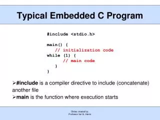
Slides created by: Professor Ian G. Harris Typical Embedded C Program #include <stdio.h> main() { // initialization code while (1) { // main code } } • #include is a compiler directive to include (concatenate) another file • main is the function where execution starts
Slides created by: Professor Ian G. Harris Header Files • Files included at the top of a code file • Traditionally named with .h suffix • Include information to be shared between files • Function prototypes • externs of global variables • Global #defines • Needed to refer to libraries
Slides created by: Professor Ian G. Harris Function Calls • Functions enable simple code reuse • Control moves to function, returns on completion • Functions return only 1 value main() { int x; x = foo( 3, 4); printf(“%i\n”, x); } int foo(int x, int y) { return (x+y*3); }
Slides created by: Professor Ian G. Harris Function Call Overhead • Program counter value needs to be restored after call • Local variables are stored on the stack • Function calls place arguments and return address on the stack main() { int x; x = foo(2); printf(“%i\n”, x); } 20: 21: 22: int foo(int x) { int y=3; return (x+y*3); } 30: 31:
Slides created by: Professor Ian G. Harris Variables • Static allocation vs. Dynamic allocation • Static dedicates fixed space on the stack • Dynamic (malloc) allocates from the heap at runtime • Type sizes depend on the architecture • On x86, int is 32 bits • On ATmega2560, int is 16 bits • char is always 8 bits
Slides created by: Professor Ian G. Harris Variable Base Representation • Base 10 is default • Base can be specified with a prefix before the number • Binary is 0b, Hexadecimal is 0x Ex. char x = 0b00110011; char x = 0h33; • Binary is useful to show each bit value • Hex is compact and easy to convert to binary • 1 hex digit = 4 binary digits
Slides created by: Professor Ian G. Harris Volatile Variables • The value of a volatile variable may change at any time, not just at an explicit assignment • Compiler optimizations are not applied to volatile variables • When can variables change without an explicit assignment? 1. Memory-mapped peripheral registers 2. Global variables modified by an interrupt service routine 3. Global variables accessed by multiple tasks within a multi-threaded application
Slides created by: Professor Ian G. Harris Volatile Example • periph is the mapped address of the peripheral status info • *periph is assigned by peripheral directly . . while (*periph != 1); // wait until data transfer . // is complete . • Compiled code will move memory contents to a register • Memory will only be moved once because *periph does not change
Slides created by: Professor Ian G. Harris Bitwise Operations • Treat the value as an array of bits • Bitwise operations are performed on pairs of corresponding bits X = 0b0011, Y = 0b0110 Z = X | Y = 0b0111 Z = X & Y = 0b0001 Z = X ^ Y = 0b0101 Z = ~X = 0b1100 Z = X << 1 = 0b0110 Z = x >> 1 = 0b0001
Slides created by: Professor Ian G. Harris Bit Masks • Need to access a subset of the bits in a variable • Write or read • Masks are bit sequences which identify the important bits with a ‘1’ value • Ex. Set bits 3 and 5 or X, don’t change other bits X = 01010101, mask = 0010100 X = X | mask • Ex. Clear bits 2 and 4 mask = 11101011 X = X & mask
Slides created by: Professor Ian G. Harris Bit Assignment Macros #define SET_BIT(p,n) ((p) |= (1 << (n))) #define CLR_BIT(p,n) ((p) &= (~(1) << (n))) • 1 << (n) and ~(1) << (n) create the mask • Single 1 (0) shifted n times • Macro doesn’t require memory access (on stack)
Slides created by: Professor Ian G. Harris Embedded Toolchain • A toolchain is the set of software tools which allow a program to run on an embedded system • Host machine is the machine running the toolchain • Target machine is the embedded system where the program will execute • Host has more computational power then target • We are using the GNU toolchain • Free, open source, many features
Slides created by: Professor Ian G. Harris Cross-Compiler • A compiler which generates code for a platform different from the one it executes on • Executes on host, generates code for target • Generates an object file (.o) • Contains machine instructions • References are virtual • Absolute addresses are not yet available • Labels are used instead
Slides created by: Professor Ian G. Harris Cross-Compiler Example COSTELLO.c intwhosonfirst(int x) { … } ABBOTT.c intidunno; … whosonfirst(idunno) … Cross- compiler Cross- compiler ABBOTT.o … MOVE R1, (idunno) CALL whosonfirst … COSTELLO.o … … whosonfirst: … Idunno, whosonfirst Unknown addresses
Slides created by: Professor Ian G. Harris Linker • Combines multiple object files • References are relative to the start of the executable • Executable is relocatable • Typically need an operating system to handle relocation
Slides created by: Professor Ian G. Harris Linker Example ABBOTT.o … MOVE R1, (idunno) CALL whosonfirst … COSTELLO.o … whosonfirst: MOVE R5, R1 … Linker HAHA.exe … MOVE R1, 2388 CALL 1547 … MOVE R5, R1 … (value of idunno) • Functions are merged • Relative addresses used 1547 2388
Slides created by: Professor Ian G. Harris Linker/Locator • Links executables and identifies absolute physical addresses on the target • Locating obviates the need for an operating system • Needs memory map information • Select type of memory to be used (Flash, SRAM, …) • Select location in memory to avoid important data (stack, etc.) • Often provided manually
Slides created by: Professor Ian G. Harris Segments • Data in an executable is typically divided into segments • Type of memory is determined by the segment • Instruction Segment - non-volatile storage • Constant Strings – non-volatile storage • Uninitialized Data – volatile storage • Initialized Data – non-volatile and volatile • Need to record initial values and allow for changes
Slides created by: Professor Ian G. Harris AVR GNU Toolchain • Cross-Compiler: avr-gcc • Linker/Locator: avr-ld • Cross-Assembler: avr-as • Programmer: avrdude • All can be invoked via AVR Studio 5
Slides created by: Professor Ian G. Harris ATmega 2560 Pins • Fixed-Use pins • VCC, GND, RESET • XTAL1, XTAL2 - input/output for crystal oscillator • AVCC - power for ADC, connect to VCC • AREF - analog reference pin for ADC • General-Purpose ports • Ports A-E, G, H, J, L • Ports F and K are for analog inputs • All ports are 8-bits, except G (6 bits)
Slides created by: Professor Ian G. Harris I/O Pins, Output Path DDRx PORTx
Slides created by: Professor Ian G. Harris I/O Pins, Input Path PINx
Slides created by: Professor Ian G. Harris I/O Control Registers • DDRx – Controls the output tristate for port x • DDRx bit = 1 makes the port x an output pin • DDRx bit = 0 makes the port x an input pin • Ex. DDRA = 0b11001100, outputs are bits 7, 6, 3, and 2 • PORTx – Control the value driven on port x • Only meaningful if port x is an output • Ex. PORTA = 0b00110011 assigns pin values as shown • PINx – Contains value on port x • Ex. Q = PINC;
Slides created by: Professor Ian G. Harris Test and Debugging • Controllability and observability are required • Controllability • Ability to control sources of data used by the system • Input pins, input interfaces (serial, ethernet, etc.) • Registers and internal memory • Observability • Ability to observe intermediate and final results • Output pins, output interfaces • Registers and internal memory
Slides created by: Professor Ian G. Harris RA0 main(){ x = f1(RA0,RA1); foo (x); } foo(x){ y = f2(x); bar (y); } bar(y){ RA2 = f3(y); } RA2 RA1 I/O Access is Insufficient • Control and observation of I/O is not enough to debug • If RA2 is incorrect, how do you locate the bug? • Control/observe x and y at function calls?
Slides created by: Professor Ian G. Harris Embedded Debugging Properties of a debugging environment: 1. Run Control of the target - Start and stop the program execution 2. Ability to change code and data on target - Fix errors, test alternatives 3. Real-Time Monitoring of target execution - Non-intrusive in terms of performance 4. Timing and Functional Accuracy - Debugged system should act like the real system
Slides created by: Professor Ian G. Harris Host-Based Debugging • Compile and debug your program on the host system, not target - Compile C to your laptop, not the microcontroller Advantages: • Can use a good debugging environment • Easy to try it, not much setup (register names, etc) Disadvantages: • Timing is way off • Peripherals will not work, need to simulate them • Interrupts probably implemented differently • Different data sizes and “endian”ness
Slides created by: Professor Ian G. Harris Instruction Set Simulator • Instruction Set Simulator (ISS) runs on the host but simulates the target • Each machine instruction on the target is converted into a set of instructions on the host • Example: • Target Instruction - add x: Adds register x to the acc register, result in the acc register • Host equivalent: add acc, x, acc: Adds second reg to third, result in the first reg
Slides created by: Professor Ian G. Harris ISS Tradeoffs • Advantages: • Total run control • Can change code and data easily Disadvantages: 1. Simulator assumptions can cause inaccuracies 2. Timing is off, no real-time monitoring - initial register values, timing assumptions 3. “Hardware environment” of target cannot be easily modeled
Slides created by: Professor Ian G. Harris Hardware Environment • PIC communicates with the switch and the RAM • Communications must be modeled to test PIC code • Simulators allow generation of simple event sequences • Responsiveness is more difficult to model
Slides created by: Professor Ian G. Harris Serial or TCP/IP Host (PC) Target (Atmega) Remote Debug/Debug Kernel • Remote debugger on the host interacts with a debug kernel on the target • Communication through a spare channel (serial or ethernet) • Debug kernel responds to commands from remote debugger • Debug kernel is an interrupt, so control is possible at any time
Slides created by: Professor Ian G. Harris Remote Debug Tradeoffs • Advantages: • Good run control using interrupts to stop execution • Debug kernel can alter memory and registers • Perfect functional accuracy Disadvantages: • Debug interrupts alter timing so real-time monitoring is not possible • Need a spare communication channel • Need program in RAM (not flash) to add breakpoints
Slides created by: Professor Ian G. Harris ROM Emulator • Common to read instructions from a separate ROM on the target • ROM emulator substitutes the ROM for a RAM with a controller
Slides created by: Professor Ian G. Harris ROM Emulator Features • Remote debugger where ROM is replaced by RAM - Debug kernel is in the RAM • Solves the “non-writable ROM” problem of remote debugging • ROM emulator completely controls the instructions - Full data access is possible • ROM emulator can contain a debug communication channel No need for a spare channel
Slides created by: Professor Ian G. Harris ROM Emulator Disadvantages • Instruction ROM must be separate from the microcontroller - No embedded ROM • There must be a way to write to the ROM - May be done with a complex sequence of reads • Alters timing, just as any debug kernel would
Slides created by: Professor Ian G. Harris In-Circuit Emulation (ICE) • Replace the microcontroller with an new one • Can select instructions from external ROM (normal mode) or internal shadow RAM (test mode)
Slides created by: Professor Ian G. Harris ICE Advantages • ICE can always maintain control of the program • - Interrupt cannot be masked • Works even if system ROM is broken • Generally the best solution
Slides created by: Professor Ian G. Harris Vcc Micro- controller Input Debouncing Buttons • Mechanical bounce in switch causes signal to bounce • Noticable at MHz clock rates • Need to wait until signal settles before sampling it 10ms input
Slides created by: Professor Ian G. Harris i = 0; while (i < settletime) { if (in == 0) i = 0; else i = i + 1; } • Reset counter • Advance counter Wait to Settle • settletime is the time a button signal must stay constant to be sure that it is settled • After a signal change, wait settletime clks • Debounce rising edge, reset counter every signal change to 0 • Need to debounce falling edge as well as rising edge
Slides created by: Professor Ian G. Harris Debouncing Code while (1 == 1) { i = 0; while (i < settletime) { if (in == 0) i = 0; else i = i + 1; } i = 0; while (i < settletime) { if (in == 1) i = 0; else i = i + 1; } // perform operation } • Wait for rising edge to settle • Wait for falling edge to settle • Perform Operation