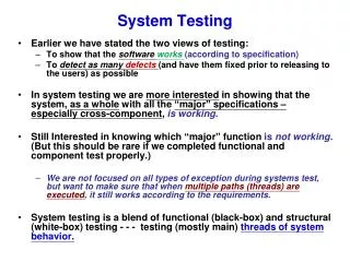
Robotic Sensor Testing - Sonar and Infrared Results
Conducted testing on robot sonar and infrared sensors by placing markers and objects at intervals to determine sensing capabilities. Results show beam width and sensor accuracy.

Robotic Sensor Testing - Sonar and Infrared Results
E N D
Presentation Transcript
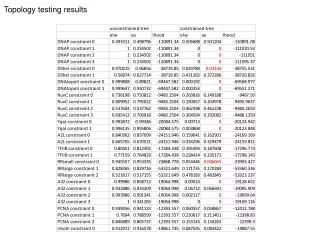
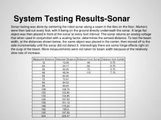
System Testing Results-Sonar Sonar testing was done by centering the robot sonar along a seam in the tiles on the floor. Markers were then laid out every foot, with 0 being on the ground directly underneath the sonar. A large flat object was then placed in front of the sonar at every foot interval. The sonar returns an analog voltage that when used in conjunction with a scaling factor, determines the sensed distance. To test the beam width, at the distances shown below, the same object was placed in the center, then moved off to the side incrementally until the sonar did not detect it. Interestingly there are some fringe effects right on the cusp of the beam. More measurements were not taken for beam width because of the relatively slow rate of increase.
System Testing Results-Infrared The infrared sensors were tested the same was as the sonars. The distance cannot be obtained as easily as it was for the sonars, however. Measurements have to be taken and a line-fit (shown below) has to be applied to find the function to determine the sensed distance.