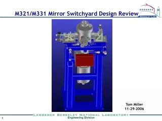
Local Switchyard
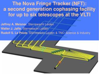
The Nova Fringe Tracker (NFT): a second generation cophasing facility for up to six telescopes at the VLTI Jeffrey A. Meisner , Sterrewacht Leiden Walter J. Jaffe , Sterrewacht Leiden Rudolf S. Le Poole , Sterrewacht Leiden & TNO Science & Industry.

Local Switchyard
E N D
Presentation Transcript
The Nova Fringe Tracker (NFT): a second generation cophasing facility for up to six telescopes at the VLTI Jeffrey A. Meisner, Sterrewacht Leiden Walter J. Jaffe, Sterrewacht Leiden Rudolf S. Le Poole, Sterrewacht Leiden & TNO Science & Industry
NFT design (shown for 6 telescopes): simplicity! Incoming beams from M1 (pick-off) PinholeMask M5 mirrors PRS M4mirrors Local Switchyard Polarization Reversers Spectral prism Wollaston prism Camera lens Detector Monolithic prism block of polarizing beam splitters Concept for the NFT proposed to ESO in 2010 by the (former) NOVA consortium which included: Back end of NFT, Not sensitive to OPD, No visibility loss possible due to alignment etc.
Outline of this talk: • Fringe-tracking requirements at the VLTI and the Phase-A studies towards a second-generation fringe-tracking facility, ESO's (non-)decision, and subsequent (in-)action • Overview of the NFT, its technological choices, and performance features • Strategies for the fringe-tracking control loop and simulation results based on the proposed NFT design. • The particular problem of “photometric crosstalk,” and the solution proposed using the Polarization-Based Collimated Beam Combiner topology: how the NFT works. • The road forward toward a 2nd generation fringe tracker at the VLTI (hopefully....)
So how did we get here? A timeline: 2009: ESO calls for Phase-A studies to propose a concept for a Second Generation Fringe Tracker for the VLTI Requirements: • Accept beams from 4 or 6 telescopes (not just 2) either from science target itself or from off-axis reference star • Measure phase for control of VLTI delay lines (fringe locking) for long coherent exposures & phase referenced imaging • Sensitive to group delay for dispersion control and fringe-jump detection • Tolerant of wavefront and photometric fluctuations • Tolerant of different (possibly small) visibilities on some baselines • Possibility of combining AT (1.8 meter telescope) with UT (8 meter telescope), 20x brighter! • Rapid update rate possible (up to 2 KHz) with best possible limiting sensitivity (of course!)
Two well developed proposals submitted in response to the call by ESO: • POPS (Planar Optics Phase Sensor) submitted by LAOG • NFT (NOVA Fringe Tracker) submitted by the NOVA consortium Concepts presented in May 2010 for ESO's consideration Meeting at ESO in December 2011 to discuss and compare the concepts, with inconclusive results. It was generally agreed that: • Theoretical sensitivity of NFT significantly higher. • Technology used in POPS proposal already had been tested and verified in on-sky interferometry, unlike that of the NFT. The road forward: no agreement at all.
Differences: NFT • Bulk optics interferometric implementation, using a novel beam-combination topology • Only partial spatial filtering using pinholes, adaptable to conditions • Ultra-wide-band (1.2 – 2.4 micron) • Direct combination of 4 baselines, other two inferred • Nominally measures single interference phase in order to generate delay-line correction POPS • Integrated optics beam-combination using a fiber-fed IO device • Full spatial filtering by virtue of using optical waveguide components • IO chip built either for K or H band • Direct combination of each of the 6 telescope pairs • Measures both quadrature phases of interference Similarities: • Both use pair-wise interference. • Both based on static measurement of interference phase (like PRIMA) rather than phase stepping/scanning (like FINITO). • Both use low-resolution spectral dispersion to detect group-delay offset while co-phasing (again, like PRIMA!).
Various concerns raised by ESO, and answered by additions to the NFT design or the NFT analysis: • Questioning of only detecting one quadrature phase, with no OPD modulation (whereas POPS detects both quadrature phases, like PRIMA). • Questioning of not obtaining photometric information (POPS can obtain the photometry of the individual telescope beams indirectly). • Questioning of how the fringe OPD sensor would drive a feedback loop to control the delay lines, as the NFT outputs did not seem compatible with the current fringe tracker paradigms. • Questioning the “risk” of employing system technologies that had never been tested on stellar light. The NFT has carefully addressed the first three concerns, and the fourth one can only be addressed (to the satisfaction of the skeptics) by doing it!
Factors driving the design of the NFT: Problem: a fringe tracker is needed to cophase 4 (or in the future 6) VLTI telescopes in order that the science instrument can coherently integrate (thus obtaining a good SNR on dim targets) and also to obtain visibility phase either with respect to an off-axis reference star or with respect to the target itself at the fringe-tracker's wavelength. Therefore the ability to perform interferometry on a faint target is dependent on the fringe-tracker's ability to lock onto its phase or the phase of a reference star found nearby. Thus the three most important performance goals driving the design of the NFT are: • Sensitivity • Sensitivity • Sensitivity
Achievement of highest limiting sensitivity (dimmest star on which reasonably reliable tracking can be performed) through: • High throughput: - Use of free space optical paths rather than integrated optics - No need for spatial filtering (fiber injection losses) but still use pinholes for spatial mode reduction in order to maximize performance (as demonstrated by simulations)- Minimal number of non-cemented optical surfaces (AR coated)Resulting throughput calculated: 85%, guaranteed: 80% • Minimize wavefront degradation before beam-overlap: - 3 reflecting and 3 transmitting surfaces including VLTI pickoff and PBS surfaceResult: calculated V=.977 at 2 m • Minimal spectral resolution (but variable) of 4 or 5 spectral channels over 1.2 – 2.4 m, just in order to gauge dispersion and fringe-jumps • In original configuration, use of only one of the two quadrature phases for interference! Full quadrature detection wastes half of the light measuring the real part of visibility which supplies no first-order information regarding OPD offset.(However doing this over a very wide band requires a more elaborate dispersion compensator than otherwise required). Partial quadrature detection available with 2011 hardware additions. • Likewise no optical power wasted on photometric monitoring which supplies no first-order information regarding OPD offset.-Variable photometric monitoring available with 2011 hardware additions. • Slower detector readout rate, when possible (but ESO requests 1-2 kHz update rates).
Incoming beams from M1 (pick-off) M5 x1 PRS align pinhole fixed M4 x1 fixed Align, coarse OPD + piezo align /2 plates PBS Spectral prism (optional) Wollaston prism Camera lens Detector NFTUpgradability Minimal configuration to verify components and performance on 1 baseline
Incoming beams from M1 (pick-off) M5's PRS M4's Mask Local Switchyard End-around combiner Polarization Reversers (rotatable) Spectral prism Wollaston prism Camera lens Detector NFTUpgradability Configuration for up to 4 telescopes.....
Incoming beams from M1 (pick-off) M5's PRS M4's Mask Local Switchyard End-around combiner Polarization Reversers Spectral prism Wollaston prism Camera lens Detector NFTUpgradability All 6 channels now installed(unless you want even more!)
Further advantages of the technological choices adopted by the NFT: • Not acutely affected by input polarization mismatches, no SNR loss at all due to birefringence between vertical and horizontal polarizations, since each pairwise beam combination only uses one or the other. • Beam overlap is performed very early in the optical chain, after which OPD shifts, vibrations, or poor optical surface quality has no effect on interferometric visibility or the measured phase of interference. • A 4 or 6 beam combining topology can be used at full efficiency with only N telescopes if N is even. Modest SNR loss if N is odd.
Delay-tracking control loop and simulation of NFT • Control loop not part of NFT proposal per se, but used in NFT simulations to demonstrate suitability of hardware. • A basic linear fringe-tracking algorithm proposed, identical to what the analog electronics in the experimental setup did: Delay line motion = gain * Im{V} (too simple!). • A complicated algorithm was developed (but this had not been a requirement of the original ESO call!) to examine the detector outputs in 2 or more spectral channels in order to detect fringe jumps and order correction jumps. Also generates a judgement of “verified tracking intervals” needed in order for a science instrument to (properly) employ the fringe-tracker's data to the fullest. This was successfully simulated. • Specifically in response to ESO, a method was developed for the detection of loss of tracking (actually several parallel indicators have been identified!), and successfully simulated.
Using a frame time of 5ms, tracking is successful at a K band photon flux of only 70,000 per second with a typical tracking rate over 80%. Periods when the tracker was locked onto a side fringe (three are shown) are detected by the tracking algorithm after typically 1/2 second, leading to a correction and invalidation of the intervals where it may not have been correctly tracking (“validated” intervals are marked in green). Well less than 1% of “validated” intervals are found to actually have been off of the intended fringe peak, causing an apparent visibility reduction in the science instrument of less than 1%. OPD is measured in femtoseconds. The left and right plots represent two different detector noise realizations when tracking the same atmospheric OPD and incident wavefronts.
1% criterion Tracking statistics predicted for 1ms detector frame rate, tracking on H & K band light
The problem of “photometric crosstalk” due to a beam-combiner lacking photometric symmetry. This is a key issue addressed by the particular topology of the NFT. An ideal 2 x 2 on-axis beam combiner: Ideal 50/50 Beamsplitter EA Detector EB E1 + - |V| cos() I1 E2 Detector I2
The problem of “photometric crosstalk” due to a beam-combiner lacking photometric symmetry. This is a key issue addressed by the particular topology of the NFT. An actual beam combiner: Ideal 50/50 Beamsplitter EA Photometriccrosstalk Detector EB E1 |V| cos()+ (IA – IB)where: = ½ (R - T) + - I1 E2 Detector I2 Visibility estimatorI1 – I2 inevitably includes a photometric crosstalk term = (IA – IB)
Naive approach to prevent photometric crosstalk: Force =0 by making the beamsplitter's T = R = ½ But: • It will not generally be constant over wavelength • It will almost always be different between the polarizations • Moreover this is difficult to do in the first place! For instance, the VINCI (fiber) beam combiner, regularly adjusted for maximum fringe contrast, had a very unpredictable (almost never near zero!) as plotted over 3 years: +.6 .4 .2 0 -.2 -.4 -.6
Cancelling photometric crosstalk term using photometric pick-offs: Split off a fraction m of the incoming optical powers, and add them in the correct proportions to the interferometric outputs. Drawbacks: • Photometric monitoring beams rob power from the interferometric channels • Added photometric corrections m IA and m IB contain their own detector noise, added to resulting visibility determination • Want cancellation in both polarizations and at all wavelengths: generally impossible! m IA A + - I1 m IB I2
Combating photometric crosstalk by chopping the phase (modulation of the OPD): This is the most common solution! For instance: ABCD phase stepping, or scanning of fringe packet • Then the visibility appears as an AC signal on the photodetector. • Just ignore the DC (and low frequencies) then. • So measure |E1+ E2 exp(j )|2 + (IA – IB) as a function of (t), and the photometric crosstalk term can be eliminated (if it stays constant!). OPD Modulator CoherentDetection Estimate of complex V A C B D(for instance) Drawbacks: • Requires more than one detector readout to measure a visibility • Since the photometrys and OPD are changing due to the atmosphere, these fluctuating components leak into the result. • In order to reduce that effect, a faster readout speed is required, reducing sensitivity in a NIR instrument.
Solution employed by the NFT: precise 50/50 beamsplitting through use of the “Polarization-Based Collimated Beam Combiner” topology! • Combines beams pairwise. • Each telescope's light is split by polarization, to be combined with 2 other telescopes. • Each combination produces 2 (or more) interferometric outputs based on balanced combination: visibility estimates are immune to photometric crosstalk! Requires 3 essential stages: PolarizationReversers(even channels only) 1 PolarizationRecombinedBeam Beam 1 Detectors Detectors 2 3 p H Beam 2 PolarizationRecombinatonStage PolarizationAnalyzer@ 45o s V p H Beam 3 V s 2-phase detection configuration shown + - Beam 4 VisibilityEstimate
Polarization Recombining Stage (PRS) • Consists of multiple Polarizing Beamsplitters (PBS) • s polarization from telescope M is paired with p polarization of telescope M+1 into same spatial mode but a different polarization (thus a different mode) • Thus the “polarization recombined beam” can proceed through various (non polarized) optical elements and both waves are affected identically • Only when they finally reach the polarization analyzer are the two waves actually interfered and directed onto 2 (or more) photodetectors 2 Original Polarization PolarizingBeam Splitters Original Polarization H 2s V 2p V 3s H 3p H 4s V 4p 1s 2p V V H H V V Polarization RecombinedBeams TelescopeBeams 2s 3p 3s 4p Important point:After the PRS, the “polarization recombined beams” no longer need to be treated according to interferometric standards. OPD variations/instability, wavefront degradation do not affect the visibility or rejection of photometric crosstalk!
3 Polarization Analyzer produces output beams implementing a balanced beamcombiner. When their powers are detected and differenced, photometric crosstalk is suppressed! Detector A Telescope 1 Telescope 2 Detector B Now tilt your head by 45o! Beam from the polarization recombination stage (PRS) has the two telescopes' light in H and V polarizations Analyze the polarizations in the A and B directions to get the opposite interference phases with equal photometric contributions! Polarization Analyzer in rotated system 45o Rotation of Coordinate System IA A = 1s + 2p 1s 2p + - B = 1s - 2p Differential Amplifier Detectors IB
Immunity to photometric crosstalk demonstrated in experiment conducted at TU Delft. Interference from He-Ne laser (left) detected using Polarization-Based Collimated Beam Combiner” topology, with added incoherent light (“photometric noise”) injected into each “telescope” beam from independently pulsating laser diodes. Cancellation of photometric noise by ratio >> 100:1 (stable over weeks) with intended interference signal retained. Pulsating laser diodes Injected “Photometric noise” He-Ne laser Coherent “starlight” split toward both “telescope beams” Polarization analyzer (PBS) at 45o and detectors “Telescope beam 1” “Telescope beam 2” Piezo
Each detector output (left) contains an equal combination of the two photometric signals, but an opposite amount of the visibility signal! A+B(photometry only) in red A-B(photometry rejected) in white Shown: actual recorded scope data of detectors (left) and sum and difference (right) while scanning the OPD. The “photometric noise” was much (~ 10x) stronger than the “starlight,” but is completely rejected in the difference signal. In locked mode (with feedback to the piezo, not shown) the same photometric rejection is present.
Modification of response by inserting an additional optical element: 45o Rotation of Coordinate System Polarization Analyzer in rotated system IA 1s 2p + - IB Original system: IA – IB = Re{V} /4 plate at 0o 45o Rotation of Coordinate System Polarization Analyzer in rotated system IA 1s 2p + - IB Detection of quadrature phase: IA – IB = Im{V} /2 plate at 22.5o 45o Rotation of Coordinate System Polarization Analyzer in rotated system IA 1s 2p + - IB Photometric detection IA = I1 IB = I2
Modification of NFT beam combiner in order to allow for (partial) detection of quadrature visibility component and/or photometry Camera Lens DetectorArray WollastonPrism Basic implementationIA – IB = Re{V} IB IB IB A = 1s + 2p B = 1s - 2p IA IA IA IBIAetc. Proposed layout on PICNIC detector: /4 plate with wedge Augmented system:I'A – I'B = Im{V}I''A = I1 I''B = I2 I'BI'A I'A etc. /2 plate with wedge Slightly deflected beams with quadrature or photometric information detected on adjacent pixels, for instance
So, adding it all up: • The VLTI and its second-generation instruments (particularly MATISSE) requires an updated fringe-tracker in order to achieve its potential. • The NOVA consortium submitted a concept which meets all of the requirements and achieves a high sensitivity (limiting magnitude). • The proposal relies on standard optical components and techniques, is easily understood and modelled. • The unique feature of the beam combiner has been tested in the laboratory and (unsurprisingly) works. • A stripped-down version for only one baseline or otherwise simplified could be easily and relatively cheaply built and tested on the sky, for further verification. • So, where does ESO go from here?
? The end
Modulation of the OPD-II Drawbacks: • Requires more than one detector readout to measure a visibility • Since the photometry (and OPD!) is changing due to the atmosphere, this fluctuating component leaks into the result. • In order to reduce that effect, a faster readout speed is required, reducing sensitivity in a NIR instrument. Example: the incoherent power spectrum (top) and coherently integrated power spectrum (bottom) of 4 consecutive VINCI observations (14 Aug. 2001) of eps sco at different framerates: MoreWhiteNoise Good! LFNoise Noisier 3384 Hz: too fast. Detector noise enhanced due to short exposure 590 Hz: too slow. Spectrum is broadened by atmospheric OPD Just right! (For this VERY bright star!)
Drift Upward Wiggle above 3 level, on fringe TrackingOK Checking Wiggle Find direction of last confirmed tracking At limit of drift, Reverse drift, increase limit in other direction LostWiggle Set limit to drift Drift Down Wiggle above 3 level, on fringe
Induced “telescope failures” simulated at these times, causing tracking failure Sprial search pattern invoked following detection of tracking failrure Green indicates intervals which have been “validated” as acceptable for use of data produced by science instrument.
A laboratory setup of the concept of the Polarization-Based Collimated Beam Combiner was carried out in order to verify and demonstrate its performance goals. Many thanks to the TU Delft applied optics department and especially to the optics technician Thim Zuidwijk for facilitating.
Laser Diodes (source of “photometric interference”) He-Ne LaserPolarization at ~ 45o He-NeLaser Detector assembly rotates about beam axis, nominally at 45o LD LD PolarizingBeamsplitters Photodiode Polarization Analyzer & Detectors Aperture Mask Photodiode PiezoStack Photodiode Photodiode Photodiode preamps, differencing circuit, Scan HVAmp (for testing) Control loopfilter - integrator Lock +
Actual application, using starlight! PolarizingBeamsplitters Beam from Telescope 1 1s + 1p Beam from Telescope 2 etc. Vertical polarizationin VLTI tunnels Polarization Reverser Polarization Analyzer at 45o 1s 1s + 2p 2s + 2p PiezoStack Detector Array And/or VLTI delay line, stroke = 120m 2s To next combiner Detector Read-out Electronics HVAmp Real-timeComputer
The signal from just a single photodetector (without balancing from the other one) showing the combined waveform of the two laser diodes (incoherent source), one at about 1KHz, the other at 4KHz. These added “photometric fluctuations” are both highly rejected by the differential amplifier when the angle of the analyzer is correctly set to 45o and the relative gains are set appropriately.
See movie 1 basic demo He-NeLaser LD LD Polarization Analyzer & Detectors ATMOSPHERE Aperture Mask CORR Photodiode PiezoStack Hot turbulent air from hair dryer Photodiode Photodiode Photodiode preamps, differencing circuit, HVAmp (for testing) Control loopfilter - integrator Lock + VPD = sin()
See movie 2 dim beam He-NeLaser Added! LD LD NeutralDensityFilter x .03 Polarization Analyzer & Detectors Aperture Mask Photodiode ATMOSPHERE PiezoStack Photodiode Photodiode Photodiode preamps, differencing circuit, HVAmp (for testing) Control loopfilter - integrator Lock + VPD = sin()
Optical disturbancefollowing PRS does not degrade visibilityor photometric symmetry See movie 3 wine glass He-NeLaser LD LD Polarization Analyzer & Detectors PRS Photodiode ATMOSPHERE PiezoStack Photodiode Photodiode Photodiode preamps, differencing circuit, HVAmp (for testing) Control loopfilter - integrator Lock + VPD = sin()