Download
1 / 28
280 likes | 461 Views
Cleaning , Vacuum & Refrigerant Charge Procedures. Monitoring Operative Parameters. Suction pressure at the compressor. Discharge pressure at the compressor. Suction temperature at the compressor (total superheat);. Discharge temperature at the compressor. Suction temperature

E N D
Cleaning, Vacuum & RefrigerantChargeProcedures
Monitoring Operative Parameters Suction pressure at the compressor Discharge pressure at the compressor Suction temperature at the compressor (total superheat); Discharge temperature at the compressor Suction temperature at the evaporator outlet (evaporator superheat) CONDENSER Liquid temperature at the expansion valve inlet (liquid subcooling) EVAPORATOR
BasicInstrumentation A basic refrigerant recovery equipment is required: A Digital Weighing Platform used to avoid overfilling the Recovery Cylinder and ensuring that the exact amount of refrigerant charged into the system can be logged. This aids monitoring of consumption and leakage. Refrigeration Storage Tank with two connection ports to enable charging of liquid and extraction of vapour simultaneously A Vacuum Pump that removes moisture and non-condensable gases after the system has been opened for maintenance and repair. Recovery Unit with oil-free compressor and pressure manometers Manifold with pressure and suction gauges and connection hoses. This gives a full overview of system performance and visually monitoring the system during refrigerant recharging. A Vacuum Gauge used to determine if proper vacuum has been obtained. It will also help indicate if the system is not leak-tight. An Electronic Leak Detector can detect up to 5 ppm and features a six-segment visual leak size indicator and a variable frequency audible alarm.
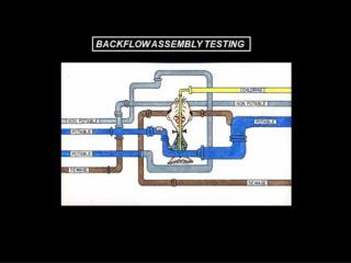
Cleaning the Refrigerant Circuit • 1) The circuit must be flushed with nitrogen in order to remove oil residues and other impurities. • 2) Close the rotalocks connections. • 3) Remove the filter drier and let both the low and high pressure sides opened. • 4) Start flushing both sided with nitrogen at least 3 times. REMOVE NITROGEN NITROGEN
Moisture in RefrigerationSystems • VisibleMoisture • Water Droplets (uncommon, but it can occur) • InvisibleMoisture • Water Vapor (found in allgases and solids) • Air in the piping • “Wet” Refrigerant • Leaks Under a Vacuum Condition • Copper and Brass Components • System componentsexposedto atmosphere duringassembly
Moisture in RefrigerationSystems • VisibleMoistureProblems • FREEZE • OBSTRUCTS THE PROPER FUNCTIONING OF THE COMPRESSOR • AND THE REFRIGERATION SYSTEM • ICE CRYSTAL FORMATION AT THE POINT OF EXPANSION • CAP TUBE BLOCKED • EXPANSION VALVE • InvisibleMoistureProblems • MOISTURE + METALS = CORROSION • MOISTURE + REFRIGERANT = ACID • CFC & HCFC & HFC: Hydrolyze to form Hydrochloric Acid orHydrofluoric Acid • Acid formation is accelerated by heat • Copper and brass will be attacked (hot surfaces and bearings) • MOISTURE + REFRIGERANT + OIL = SLUDGE • REDUCE SERVICE LIFE AND INCREASE CONDENSING PRESSURE • HIGH DISCHARGE PRESSURE AND TEMPERATURE • MECHANICAL AND ELECTRICAL COMPRESSOR FAILURE
Vacuum • How can we get the water out? • Wemustboilit • We can’t raise the system temperature to 100 °C. • We can lower the system pressure to a point that water boils at ambient temperatures (vacuum ) Measured pressure Absolute pressure Positive pressure Atmospheric pressure (0 barg or 1.013 bara) Differential pressure Negative pressure (vacuum) Absolute vacuum Zero absolute pressure
Vacuum Basic Physics: AS PRESSURE DECREASES, THE BOILING POINT DECREASES 1.013 bara 0.98 bara 100 °C 26 °C
VacuumPump • Two stage rotaryvacuumpumps • most common for service; • largercubicmeter per minute capacity; • slightly heavier than single stage of samecapacity; • can achieve deeper vacuum than single stage because second stage takes over at the level first stage stops; • can pull to one micron of Mercury vacuum. 2nd stage 1st stage
Vacuum Procedure First of all, the compressor must be isolated from the system. It is essential to connect the vacuum pump to both the LP & HP side in order to avoid dead-ending parts of the system. Pull down the refrigeration circuit under a vacuum of: R407C, R410A 0.1 mbar (10 Pa, 0.075 Torr) R22 1 mbar (100 Pa, 0.75 Torr) • Low-pressure gauge • (B) High-pressuregauge • (C) Slowly open • (D) Vacuum pump turn on
Vacuum Procedure 3) When the correct vacuum level is reached, the circuit must be isolated from the pump. 4) Wait at least for 30 minutes. 5) If the pressure rapidly increases, then the circuit is not leak tight. Locate and repair leaks. Restart from step 1). If the pressure slowly increases, then the circuit contains moisture. Break the vacuum with nitrogen gas and repeat steps 1), 2), 3). Leakage Moisture Pressure [bar, Pa, Torr] Vacuum level Tight & dry Time [min] The vacuum levelshould be reached and maintained for at least 4 hours (it depends on the length and size of the circuit): it will guarantee that the circuit is both tight and fully dehydrated.
RefrigerantCharge Zeotropic refrigerant mixtures (i.e. not defined by a single pressure-temperature relationship) such as R407C must always be charged in liquid phase. For the initial charge, the compressor must be stopped and service valves must be closed. Charge refrigerant as close to the nominal system charge as possible before starting the compressor; then, slowly add refrigerant in liquid phase on the low-pressure side, as far away as possible from the running compressor. Connections size for R22-R407C-R410A: 1/4“
RefrigerantRuler The refrigerant ruler is used to calculate the pressure and temperature of refrigerants. Set the cursor on the refrigerant pressure and read off the corresponding temperature. The values are shown in metric and US units.
Subcooling Subcooling is defined as the difference between the refrigerant liquid temperature and its saturation temperature. It can be used to check the correct refrigerant charge. Subcooling can bemeasuredby: placing a thermometer on the expansion valve inlet, reading the liquid temperature Tliq. placing a pressuregauge on the inlet (or outlet) of the condensercoil, reading the condensingpressurepcond. Thispressureisstrictlylinkedto the saturation temperature of the refrigerantTsat cond (bubblepoint temperature ifzeotropicmixtures, likeR407C). Pressure gauge pcond Tsat cond Tsat cond – Tliq= SBC ≈ 5 – 10 °C Thermometer Tliq
Superheat Superheat is defined as the difference between the refrigerant vapor temperature and its saturation temperature. It can beusedto monitor the functioningof the expansion valve. Superheat can bemeasuredby: placing a thermometer on the evaporator outlet, reading the vapor temperature Tvap. placing a pressuregauge on the evaporator outlet, reading the evaporatingpressurepevap. Thispressureisstrictlylinkedto the saturation temperature of the refrigerantTsat evap(dewpoint temperature ifzeotropicmixture, as R407C). pevap Pressure gauge Tasp Thermometer Tsat evap Tasp – Tsat evap= SPH ≈ 5 °C
Pump Down Procedure When a leak is detected or a compressor replacement is required, it could be useful to perform a “pump down” procedure. The term means the operation by which all the refrigerant inside the circuit is pumped on the high pressure side (i.e. on the condenser side), making it possible both to operate on the low pressure side and to recover the major amount of refrigerant.
Pump Down Procedure Close the shut off valve placed after the liquid receiver at the output of the condenser coil. Let the compressor run until the low-pressure manometer goes down to 0.5-1 bar; the lower is this pressure, the minimum is the refrigerant loss. 0.5-1.0 bar CLOSED ON
Pump Down Procedure 3) Switch the main circuit breaker off. 4) Close the rotalock on the discharge side of the compressor; if the compressor miss rotalocks, close the shut off valve on the high pressure side. CLOSED OFF
RemovingLiquidRefrigerant • Remove the refrigerant from the HP side of the system through any connection or valve located on the liquid line by using a refrigerant recovery unit and storage tanks. • Make a note of the weight of refrigerant mass reclaimed. OFF
Lubrication & Oil Adjustment Compressor oil drain • Open the suction port, or the sight glass port (when fitted); • Move the compressor slowly to a horizontal position and recover the oil through the compressor suction connection port, or from the oil sight glass opening. • Note: the large scroll compressor is equipped with an oil drain connection and can therefore be drained of its lubricant in a vertical position. In this case, pressurize the LP side of the compressor (by using dry nitrogen). • Pick an oil sample for analysis if needed (i.e. operational installation). • Before re-installing the compressor, or replacing the sight glass, replace the gaskets by new ones (suction & discharge ports, sight glass gasket). Check the old lubricant for acid content using an acid test kit. • Install a new filter drier. An anti-acid type cartridge has to be used if the acid test is positive. The anti-acid filter drier has to be replaced by a standard cartridge after a few days when the system is acid free. Oil drain
Lubrication & Oil Adjustment It is not required to add oil whenever the refrigerant lines don’t exceed 30 meters. When the lines exceed 30 meters, and vertical lines are also present, it is advisable to add oil according to the number of siphons along the gas line. Fill in with water one siphon, pour it in a graduate cup and multiply this quantity for the number of siphons: this is the amount of oil to add to the system. NO OK! NO
Lubrication & Oil Adjustment • Additionalrecommendations • • After adding oil, allow the compressor to run fully loaded for 20 minutes and re-check the level in the oil sight glass. This level should be between 2/4 and 3/4. • • Be careful not to add more oil than necessary. The following adverse conditions can occur if excessive oil ispresent: • - Failure of valves and pistons or scroll involutes due to oil slugging. • - Excessive carry over of oil loss of evaporator performance due to oil level built-up in the low side of the system.