Download
1 / 26
260 likes | 396 Views
This paper presents a novel computational model for enhancing inference chains within expert systems, particularly those reliant on rule-based knowledge storage. It addresses the challenges posed by NP-complete problems that often hinder computational efficiency. The introduction of Boolean algebra and logic networks allows for a more efficient inference process, vital in real-time, safety-critical applications. By employing a four-valued logic system, the model accommodates uncertainty and improves the handling of complex rules, ultimately enhancing performance and reducing computation time in expert systems.

E N D
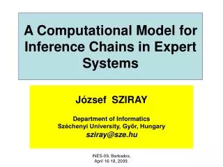
A Computational Model for Inference Chains in Expert Systems József SZIRAY Department of Informatics Széchenyi University, Győr, Hungary sziray@sze.hu INES-09, Barbados, April 16-18, 2009.
1. Introduction • In many cases, artificial intelligence is realized within the frames of expert systems. It is a computationally feasible, practical approach. • The most common form of storing knowledge in expert systems is the use of rules. It means that the knowledge baseconsists of rules and facts. The other keycomponent of such an expert system is the inference engine. • The major concern related to the inference processes is their excessive computational amount. The task to be solved belongs to the so-called NP-complete problems. INES-09, Barbados, April 16-18, 2009.
NP-completeness:Nondeterministic PolynomialComplete, - an extremely important class of computation theory. NP-complete problems have a computational complexity for which there exists no upper bound by a finite-degree p(n)polynomial of the problem sizen. The number of the computational steps is finite, but unpredictable. In most cases, it is an exponential function of n. Problem size of a rule based expert system: The number of the rules (n). INES-09, Barbados, April 16-18, 2009.
In case of real-time safety-critical(embedded) systems the reaction time for the external events is a key issue. It means that the speed of the calculations is a critical factor. The same applies to the memory consumption, which is also limited in embedded systems. Expert systems have gained a wide-spread use in controlling railway stations, dangerous chemical processes, airplane flights, medical systems, etc. These applications are equally related to safety-oriented systems. INES-09, Barbados, April 16-18, 2009.
2.Fundamental Concepts • The basic syntax of a rule is: IF <antecedent> THEN <consequent>. Anexample: IF the spill is liquid AND the spill pH < 6 AND the spill smell is vinegar THEN the spill material is acetic acid INES-09, Barbados, April 16-18, 2009.
Classical expert systems build up the knowledge base in a usual data-base structure, and their inference engine applies an exhaustive search through all the rules during each cycle. Consequence: systems with a large set of rules (over 100 rules) can be slow, and thus they are unsuitable for real-time applications, especially in the field of embedded environment. A new knowledge representation which is based on Boolean algebra and logic networks will be introduced. Result: a significantly more efficient inference processing than the classical one. INES-09, Barbados, April 16-18, 2009.
3. The Use of Boolean Algebra and Logic Networks • It can be easily seen that the logic conditions within the rules can directly be substituted by the corresponding Boolean operations and logic gates. As an example let us consider the following set of rules, where the facts are denoted by capital letters: IF C AND D THEN L, IF NOT E THEN K, IF L OR K THEN P, IF E AND M THEN Q. INES-09, Barbados, April 16-18, 2009.
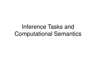
The Boolean description of the above rules is the following: L = C · D, K = E’,P = L + K, Q = E · M. These four rules can be represented by four logic gates: two AND gates, one NOT gate, and one OR gate. Now, if we connect the inputs and outputs of these gates in accordance with the identical letters, the logic network of Figure 1 will be obtained. INES-09, Barbados, April 16-18, 2009.
C L P D K E Q M Figure 1. The logic network for the rule base INES-09, Barbados, April 16-18, 2009.
It should be noted that in case of a simpledirect rule, for example, IF U THEN V, its corresponding Boolean form will be V = U. • This relation is represented by a YES gate which does not modify its input value. INES-09, Barbados, April 16-18, 2009.
4. The Use of a Four-Valued Logic System If a fact is true in the inference process, then its logic variable will have the value 1, if it is false then its value is 0. However, as far as the general algebraic treatment of rule bases is concerned, it requires more than these two values. It can be proved that the number of necessary and sufficient values is four. It means that in addition to 0 and 1, two more values are to be involved. These are as follows: INES-09, Barbados, April 16-18, 2009.
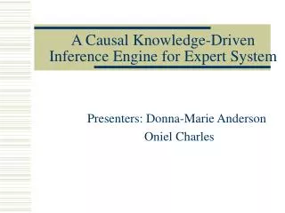
1) The indifferent or don’t care logic value: d. The network line which carries this value can take on either 0 or 1 freely, without influencing the computational results. 2) The unknown logic value: u. We have not any knowledge about the concrete logic value (0, 1 or d) of the network line carrying u. The treatment of the four values can be extended to the basic Boolean operations. The truth tables are shown in Table 1: INES-09, Barbados, April 16-18, 2009.
OR 0 1 d u 0 1 d u NOT AND 0 1 d u 1 0 d u 0 1 d u 0 0 0 0 0 1 d u 0 d d u 0 u u u 0 1 d u 0 1 d u 1 1 1 1 d 1 d u u 1 u u Table 1. Truth tables of the four-valued logic system INES-09, Barbados, April 16-18, 2009.
C L P D K E Q M Figure 1. The logic network for the rule base INES-09, Barbados, April 16-18, 2009.
The forward chaining procedure: • Example (Figure 1): The initial set of facts: T0 = {A, B, C, D, E, G, H}. • Step 1: C = 1 and D = 1, since they both are in the fact base, which results in L = 1, so L is placed in the fact base. • Step 2: E = 1, because E is in the fact base, from which it follows that K = 0, but L = 1 alone implies P = 1, so P is placed in the fact base. INES-09, Barbados, April 16-18, 2009.
Step 3: The fact base does not contain M. In our logic system it can be interpreted as M = u. Though E = 1, due to the unknown value of M, this is not sufficient to imply Q = 1. It means that Q = u, thus Q cannot be placed in the fact base. • Here the final conclusion of the forward chaining was that fact P is true alone. • The above computational procedure can also be called forward tracing of the logic values. It means that we calculate the output values of the logic gates with knowledge of the gate-input values. INES-09, Barbados, April 16-18, 2009.
The backward chaining procedure: • The backward chaining procedure involves backward tracing of the logic values through the network. Now the input values of a gate have to be determined with knowledge of the actual gate-output value. In this case the goal is to justify that a primary output value is 1, i.e., a selected fact is true. It requires a successive decision process which is also called line-value justification. • As known, line-value justification is a procedure with the aim of successively assigning input values to the logic elements in such a way that they are consistent with each previously assigned value. INES-09, Barbados, April 16-18, 2009.
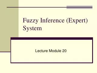
The backward tracing of the logic values can also be performed in accordance with the four-valued truth table. • Problem: For a given output value at a gate not only one input combination can be assigned, there may be more than one possible choices. If two-input gates are considered, the possible choices are summarized in Figure 2 and Figure 3. INES-09, Barbados, April 16-18, 2009.
No solution exists 1 1 1 0 d 0 u 1 u d 0 u 0 u 1 1 0 0 Figure 2. Backward tracing choices for an AND gate INES-09, Barbados, April 16-18, 2009.
No solution eexists 0 0 u 1 d 1 u u 0 d 1 u 1 0 0 0 1 1 Figure 3. Backward tracing choices for an OR gate INES-09, Barbados, April 16-18, 2009.
Some viewpoints: • Only the determined logic values, 0 and 1, have to be traced back. Only these values are to be justified at the gate inputs. The value of d needs no justification. The output value of u is justified only by the input values of u. • Since d does not require justification, it is worth assigning the minimum number of determined values to the gate inputs, while leaving the others at the value of d. • In this logic system, the determined values and u are consistent only with d. Whenever a contradiction, i.e., inconsistency occurs, we have to make a new choice or change the last possible decision. INES-09, Barbados, April 16-18, 2009.
C L P D K E Q M Figure 1. The logic network for the rule base INES-09, Barbados, April 16-18, 2009.
Example (Figure 1): Initial set of facts: T0 ={A, B, C, D, E, G, H}. • Step 1: The proof of P = 1: At first let K = 1 and L = d, which are the minimally necessary assignments. Now from K = 1 it follows that E = 0, which is a contradiction, for E is in the fact base, so E = 1 holds. • Step 2: We have to modify our previous decision: Now let L = 1 and K = d. In this way L = 1 is justified by C = 1 and D = 1, without any contradiction. • Step 3: It is unnecessary to trace back the value K = d, since the indifferent value does not require justification. So the proof of P has been finished. • Step 4: The proof of Q = 1: This condition requires that both inputs to the AND gate be 1, i.e., E = 1 and M = 1. Since E is a member of the fact base, E = 1 holds. However, M is missing from the fact base, which means that M = u. In this case it is impossible to justify (prove) that Q = 1. INES-09, Barbados, April 16-18, 2009.
5. Concluding remarks • The conventionally organized knowledge bases apply usual data-base structures, where the computations are performed on this sructure. • In comparison with the conventionally organized knowledge bases, the calculations using this four-valued logic can advantage-ously be organized and carried out in embedded computing systems due to the following reasons: INES-09, Barbados, April 16-18, 2009.
The storage requirement of the four logic values at the network lines is negligible: only two bits are necessary and sufficient for encoding them. • Computations among logic values are ab ovofast and efficient. This fact manifests itself especially when bit-level implement-ation is applied. INES-09, Barbados, April 16-18, 2009.
The data-base structure of a logic network is comparatively simple. Only the gate types and the input-output connections of the gates are to be encoded and stored. The forward and backward tracing are carried out directly on this network structure. • The computational improvement is estimated to be at least two orders of magnitude, which is due to the required small memory space and fast operations in the logic domain. INES-09, Barbados, April 16-18, 2009.