Download
1 / 5
50 likes | 187 Views
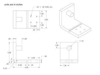
units are in inches. face 1. face 5. face 2. face 4. face 3. point 3. point 5. point 1. point 2. point 6. point 4. You are to add GDT (by hand) to the blank drawing as follows: The principal datum is to be face 1. This face should be machined so that it has a smoothness of . 003".

E N D
face 1 face 5 face 2 face 4 face 3 point 3 point 5 point 1 point 2 point 6 point 4
You are to add GDT (by hand) to the blank drawing as follows: • The principal datum is to be face 1. This face should be machined so that it has a smoothness of .003". • The secondary datum is the axis along the countersunk hole. The diameter of the thru hole must be 0.40” plus or minus 0.01”. The countersink must have a diameter in the range of 0.86” to 0.90” with a depth of 0.27” plus or minus 0.01”. The chamfer at the top of the hole must have a diameter of 0.93” plus or minus 0.01” with an angle of 90 degrees plus or minus 1 degree. The hole must meet a perpendicularity tolerance of a diameter of 0.02” relative to the primary datum. • .75" diameter cylinder. The cylinder must be machined so that its diameter is within plus or minus .008" of .75" and its center axis meets a perpendicularity tolerance of diameter .005" relative to datum A, regardless of feature size. • The tertiary datum is face 2. This face should be machined so that it meets a perpendicularity tolerance of .0075" relative to datums A and B.
The four holes should meet a position tolerance of a diameter of .025" at maximum material condition. The diameters of these holes should be within plus or minus .005" of .20". • The profile of the slot between points 1 and 2 must be within a tolerance zone of .002". • Face 3 must meet a perpendicularity tolerance of .01" relative to datums A, B, and C. • The outer edges of the front face between points 3 and 4 must meet a profile tolerance of .05". • The length of the .75" diameter cylinder must be within plus or minus .01" of 1". • Faces 4 and 5 must meet a perpendicularity tolerance of .05" relative to datums A, B, and C.