Download
1 / 29
300 likes | 470 Views
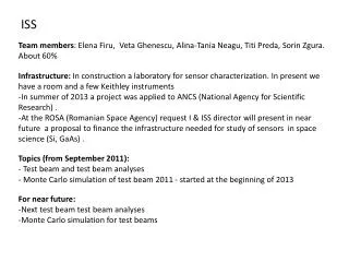
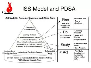
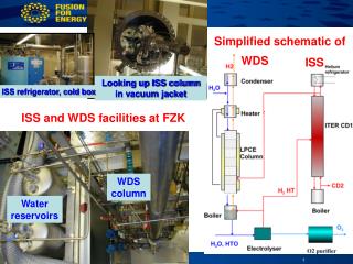
Simplified schematic of. WDS. ISS. ISS and WDS facilities at FZK. Looking up ISS column in vacuum jacket. ISS refrigerator, cold box. WDS column. Water reservoirs. 12 m LPCE. O 2 gas processing: MS dryers Wet strippers. Electrolyser. Emergency tanks.

E N D
Simplified schematic of WDS ISS ISS and WDS facilities at FZK Looking up ISS column in vacuum jacket ISS refrigerator, cold box WDS column Water reservoirs R. Laesser, F4E ITER Department
12 m LPCE • O2 gas processing: • MS dryers • Wet strippers Electrolyser Emergency tanks Tanks for H (>100Ci/kg), M, L, LL (<1.6 µCi/kg) level water Water Detritiation System (EU) • Purpose of Water Detritiation System: To use the CECE (Combined Electrolysis Catalytic Exchange) for detritiation of water (20 kg/h@10 Ci/kg) via • cracking water into hydrogen and oxygen, • stripping the residual tritium from the hydrogen before its release. • The tritium is returned to the FC via ISS. • Several potential sources of tritiated water exist in ITER. The largest routine contributors to the WDS feed streams are the Atmosphere and Vent Detritiation Systems. R. Laesser, F4E ITER Department
A few topics addressed in Working Group 7 (Tritium Plant) during the ITER Design Review • Tritium Building Layout • Modification of HVAC, ADS and VDS • Tritium Tracking Strategy R. Laesser, F4E ITER Department
Tritium Building Layout • New building layout required due to French law for • Compartmentalization (segregation of tritium inventories), • Fire zoning, • Too long escape routes, • Missing air locks, • Etc. R. Laesser, F4E ITER Department
Generic Site Tritium Plant Building Layout (ITER FDR 2001) • Dimensions Length: 79 mWidth: 20 mHeight: 34 m • Outdated design: • New regulations: • Escape routes not clear and too long. • Airlocks not included consistently. • HVAC to be changed. • Increase of width and length. • Stairways: 2 3 • Elevator: 0 1 12/29 R. Laesser, F4E ITER Department
New Tritium Plant Building Layout: French Rules • Tritium inventory segregation requires rearrangement and even splitting of primary systems (SDS SDS1+2). • WDS and ISS now next to each other. • Vacuum pumps: B1 L1. • Confinement sector / fire sector basically on floor by floor basis -700 gin a “confinement / fire sector” • Physical limitation wherever possible -70 g in a single “fire zone” (component) • Physical limitation wherever possible • Storage and Delivery System (SDS) & Long Term Storage (LTS) getter beds • Isotope Separation System (ISS, 250g > 70 g) impossible to subdivide, requires additional protection against loss of primary confinement (fire) B1 VPS: Vacuum Pumping System, CPS: Coolant Purification System 13/29 R. Laesser, F4E ITER Department
Modification of HVAC, ADS and VDS • Complexity of HVAC and confinement systems for ITER Tokamak Complex grew over years: • Overall configuration became very complex, • Concept of 90% HVAC air recycle considered to be unworkable: human access restricted due to limited fresh air throughput of HVAC systems), • Danger of cross contamination R. Laesser, F4E ITER Department
Generic ITER HVAC, Depression and Detritiation Systems Configuration: 15/29 R. Laesser, F4E ITER Department
ITER Detritiation System Block Diagram ITER Detritiation System Block Diagram 17/29 R. Laesser, F4E ITER Department
15 kg H2OL Wet Stripping Column for Tritiated Water Removal H2OL Air+H2OV • Counter current removal by exchange oftritiated water in a wet stripping column • Diameter about 0.7 m, length about 5 m • Throughput about 1500 m3h-1 • No regeneration cycles as formolecular sieve beds • Less complicated configurationand number of valves • No dryer system required • 1 column instead of 3 molecular sieve beds • Potential cost savings • Capital costs / operational costs • R&D ongoing at Mendeleyev University, Moscow • Pilot plant tests scheduled later in Japan HTOV + H2OL H2OV + HTOL Air+HTOV HTOL 18/29 R. Laesser, F4E ITER Department
ITER Ventilation and Confinement Concept • Primary confinement can include more than one barrier • Glove box (GB) for maintenance purposes. • GB atmosphere detritiation. • Secondary confinement comprises sub-atmospheric pressure control and atmosphere detritiation ISS TEP 16/29 R. Laesser, F4E ITER Department
Tritium Tracking Strategy • Tritium inventory in Mass Balance Areas (MBA-1 for FC, MBA-2 for LTS) must be known. • Tritium transfer between MBAs must be measured. • Accountancy techniques: • pVT-c (gas) • Calorimetry (gas and metal tritides) • Scintillation (gas and liquid) R. Laesser, F4E ITER Department
Tritium Inventory at any Selected Time • Assume monthly checking. Tn = Tn-1 - TBu - TD - TL + TI + TBr • Tn-1: total tritium inventory of previous month • TBu: tritium burned • TD: tritium lost by decay • TL: tritium leaving plant in effluent streams: negligible under normal operation • TI: tritium imported • TBr: the tritium bred: negligible • Burnrate = 5.90 10-07 mole T/s per MWF. • T burned/pulse = 0.35 g 7 g/day for 20 short pulse (450 s) • In 10 years: external tritium supply: total of 6.7 kg. Total amount burnt: 4.3 kg R. Laesser, F4E ITER Department
The tritium inventory at ITER site in MBA-1 can be divided in four parts: Min: tritium mobile in-vessel;Tin: tritium trapped in-vessel; Mex: tritium mobile ex-vessel;Tex: tritium trapped ex-vessel. Global tritium inventory procedure will assess these categories Mobile tritium external to Vacuum Vessel will be collected in SDS beds and measured. Tritium trapped ex-vessel will be estimated/calculated. After stop of plasma operation, mobile in-vessel tritium will be removed via wall conditioning, baking, etc., transferred via TEP and ISS to SDS and measured by in-bed calorimetry. Tritium Tin trapped in-vessel after cleaning is computed by difference using calculated Tn value. Approximately 10 days were found to be needed for the global tritium inventory procedure. Tritium tracking accuracy will also depend on the accuracy of the tritium amounts Known to be in the in-vessel components moved to Hot cell. Burnt in fusion reactions (to be determined by diagnostics) Tritium Tracking Strategy R. Laesser, F4E ITER Department
Comments to Tritium Tracking • High uncertainty in daily tritium measurements will limit significantly the availability of ITER. • The most important error is related to the measurement of fusion power needed to calculate the amount of tritium burnt. • 2 calorimeters in the LTS will reduce the error on the imported tritium with possibility of eliminating systematic errors in these measurement (theory of combining measurements). • The main factor that determines the errors in tritium inventories is the analytics employed: • Integral measurements should always be preferred, • Calorimetry is by far the most accurate method for tritium inventory measurements (0.5% accuracy). • Ex-situ measurements of the tritium trapped in removed in-vessel materials should help in the evaluation of the total tritium trapped in-vessel and reassessing this value. • Vacuum vessel in-situ sampling techniques might be even better, but will they be available? R. Laesser, F4E ITER Department
Tritium in Plasma Facing Components • JET experience clearly demonstrated that high amounts of fuel (deuterium and tritium) are trapped in co-deposited layers with large ratios of D and T over C ((D+T)/C), especially in the shadowed areas of the machine. • Extrapolation to ITER conditions indicates that in ITER the administrative limits for recovery of tritium would be reached after a very limited number of shots. • In conclusion: Carbon during DT phases in ITER must be avoided. • Even in a Be/W environment the number of plasma shots will be limited, however far higher. Tritium inventories and dust production will remain critical issues. • An all metal first wall (no carbon) is also a very positive development for the ITER Tritium Plant as the hydrocarbons will become an impurity category of minor importance. R. Laesser, F4E ITER Department
Canadian + Korean Inventory without supply to fusion Tritium supply and consump-tion during life of ITER Canadian + Korean Inventory with ITER Updated projections of Canadian + Koreantritium supply and consumption using ITER current schedule. (from Scott Willms [March 2007]). This slide was presented by Prof. M. Abdou in the presentation “Fusion Nuclear Technology Development and the Role of CTF (and ITER TBM)” at the Workshop on CTF, Culham, U.K., 22-23 May 2007. R. Laesser, F4E ITER Department
Test Blanket Modules (TBMs) in ITER • In the present European fusion program ITER is the only interim step to check the performance of future breeding blankets by means of DEMO relevant Test Blanket Modules (TBMs) in a fusion environment prior to their use in DEMO. • ITER device is a test facility for the TBMs. R. Laesser, F4E ITER Department
ITER Test Port (Equatorial plane) EU TBMs FZK CEA Installation and Testing of TBMs in ITER • 2 EU blanket concepts (HCLL and HCPB BBs) will be tested in ITER. • 4 TBMs per concept, each dedicated to one of the major ITER operational phases (H-H, D-D, low D-T and high D-T), will be fabricated and tested during the first 10 years of ITER operation. • Auxiliary systems: He purge and tritiumextraction systems, Helium Coolant System (HCS) and Coolant Purification System (CPS) are required. • EU TBMs shall be ready from first day of ITER operation. R. Laesser, F4E ITER Department
Tritium Processing in TBMs • Although very small, the amount of tritium bred in TBMs needs to be extracted, recovered and transferred into the inner DT-fuel cycle, with the main aim of: • validating the theoretical predictions on tritium breeding, • qualifying technologies and components for tritium processing, • validating the theoretical predictions on tritium recovery performance and tritium inventory in the functional/structural materials. R. Laesser, F4E ITER Department
33 mg/d HT* 257 g/d H2 to T storage and delivery (SDS) TES a c coun t anc y TBM ISS Q2 TEP HCS CPS 1.3 mg/d HT 1.9 g/d H2 Q2O VDS WDS Off-gas release Integration of TBM in the ITER Fuel Cycle He: 0.4 g/s He: 0.4 g/s He: 1.4 kg/s He: 0.35 g/s TEP: Tokamak Exhaust Processing HCS: Helium Cooling System TES: Tritium Extraction System CPS: Coolant Purification System VDS: Vent Detritiation System WDS: Water Detritiation System ISS: Isotope Separation System *High duty DT phase; 1.16E-6 g/s of T produced in HCPB-TBM R. Laesser, F4E ITER Department
mol. sieve beds (TSA) U-getter mol. sieve bed Conceptual Design of TES for HCPB-TBM Main components - Adsorption column for Q2O removal operates at RT in adsorption phase - Two bed TSA system for Q2 removal - U metal getter as scavenger bed in a by-pass line to be used mainly in the low duty DT phase HCPBTBM R. Laesser, F4E ITER Department
cat. ox., step 1 cryo-mol. sieve beds (PTSA), step 3 mol. sieve bed (PTSA), step 2 Conceptual Design of CPS for HCPB-TBM Three Step Process 1) oxidation of Q2 to Q2O and of CO to CO2 by an oxidising reactor (Cu2O-CuO) operated at 280°C; 2) removal of Q2O by two bed PTSA operated at RT and 8 MPa and at 300°C and 0.1 MPa in regeneration; 3) removal of the impurities in HCS by a two-bed cryogenic PTSA No Q2O is released from CPS to TEP (or VDS) because of the presence of metallic reducing beds in the PTSA regeneration loop R. Laesser, F4E ITER Department
Tritium Processing in DEMO • DEMO relies on enough tritium production in breeding blankets (Tritium Breeding Ratio (TBR): >1.0) R. Laesser, F4E ITER Department
The DEMO Fuel Cycle: A few Numbers • In ITER DT fuel flow rates: 120 Pam3/s (up to 200 Pam3/s. • In DEMO, despite the 7 times larger power than in ITER, only slightly higher feed flow rates are expected due to the better burn-up efficiency. • In DEMO: • ~35 kg tritium per day to be supplied for plasma operation • ~500 g of tritium burnt per day • ~550 g of tritium bred in the BBs (TBR=1.1) per day • 50 g of tritium can be added to the long-term storage each day R. Laesser, F4E ITER Department
External T needed for start D from external sources Fuelling Systems (FS): Pellet Injection, Gas Puf. Protium Release Storage and Delivery System (SDS) BB WDS Neutral Beam Injection (NBI), Cryo Pumps BB tritium recovery syst. DEMO Torus Tritiated Water Isotope Separation System (ISS) Analytical System (ANS) DT Breeding Blanket Tritium Recovery Syst. Leak detection system Q2 Release of detritiated gas via VDSs, HTO of VDSs to BB WDS Tokamak Exhaust Processing (TEP) Roughing Pumps (RP) Tritium Plant Simplified block diagram of DEMO Fuel Cycle Main changes with respect to ITER inner Fuel Cycle: main Q2 bypasses ISS and SDS. No WDS in inner FC (all HTO treated in BB Tritium collection loop. No cryopumps (with exception of NBI) shown (needs to be assessed). BB tritium recovery systems will be discussed later. R. Laesser, F4E ITER Department
Main Parts of Inner D/T DEMO Fuel Cycle • DEMO Cryopumps: If higher pressures in the DEMO divertor can be tolerated, the cryopumps could be replaced by mechanical (Roots) pumps with the benefits of continuous vacuum operation (lower inventories, smaller cryoplant). To be assessed. • DEMO Impurity Processing System: will be similar to ITER TEP, however smaller. • The Q2 permeated through the first stage of TEP will be transferred directly to the Fuelling System bypassing ISS and SDS. • The Q2 gases from the second and third stages of TEP will be sent to ISS and after isotope enrichment to SDS. • DEMO Isotope Separation System (ISS): • DEMO ISS of inner loop will be smaller than in ITER ISS as most of the recycled Q2 will bypass ISS. • Due to the lower throughput and lower inventories it should be possible to produce pure H2, D2 and T2 gases. In this way isotopic composition changes of gas mixtures during delivery from metal tritide storage beds will be avoided. • DEMO Storage and Delivery System: The tritium and deuterium storage beds could be very similar to the ones of ITER (designed for in-situ calorimetry and high supply rates). • DEMO Analytical System: will serve the inner and the BB loop. • DEMO Fuelling Systems: similar in design as in ITER (wait for ITER experience). • The inner DEMO fuel Cycle loop may not need a Water Detritiation System (WDS). All water created there can be treated in the WDS of the BB loops. R. Laesser, F4E ITER Department
Simplified Block Diagram for the Blanket Tritium Processing in DEMO He + (Q2 + Q2O) 0.4 kg/s, 0.11 MPa Q2 = 110 Pa; HT = 016 Pa Q2O = 0.16 Pa Q2O 2 kg/d 49500 Ci/kg DEMO Blanket Pth= 3.0 GW GT= 385 g/d TES η=0.9 BB TEP Q2 17.1 kg/d HT: 202000 Ci/kg BB ISS He + (Q2 + Q2O) 0.4 kg/s, 0.11 MPa Q2 = 110 Pa; HT = 1.6 Pa Q2O = 1.6 Pa Tritiated impurities BB TEP Tperm= 15 g/d He+(Q2+Q2O) 2400 kg/s, 8 MPa Tin 300ºC Tout 500ºC • Main subsystems of breeding blanket tritium recovery loops in DEMO: • Collection of HTO • Collection of HT • Processing of highly tritiatedHTO • ISS, WDS and TEP He + (Q2 + Q2O) 2.4 kg/s, 8 MPa, Q2 = 1000 Pa; HT = 0.8 Pa Q2O = 50 Pa CPS η=0.9 HCS He + Q2 + Q2O 2.4 kg/s, 8 MPa, H2 = 1000 Pa; HT = 0.08 Pa H2O = 50 Pa BB WDS Q2O 122 kg/d 1100 Ci/kg R. Laesser, F4E ITER Department
Acknowledgements Many thanks to the colleagues and principal investigators in the Associations and Industry who contributed to the development of the DT Fuel Cycle. Thanks to the contributors to this presentation, in particular: M. Abdou, N. Bekris, I. Cristescu, I.R. Cristescu, Ch. Day, M. Glugla, S. Grünhagen, D. Murdoch, G. Piazza, Y. Poitevin and I. Ricapito. END R. Laesser, F4E ITER Department