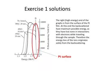
Exercise 3. Solutions
Exercise 3. Solutions. From Fujio Kida, JGC Co. All cases Write on where throughput manipulator (TPM) is located Is the system consistent? If “yes”, is it local-consistent? If “no” propose a fix. TPM = ”unused” degree of freedom that affects the throughput.

Exercise 3. Solutions
E N D
Presentation Transcript
Exercise 3. Solutions • From Fujio Kida, JGC Co. • All cases • Write on where throughput manipulator (TPM) is located • Is the system consistent? • If “yes”, is it local-consistent? • If “no” propose a fix TPM = ”unused” degree of freedom that affects the throughput. Usually set by the operator (manual control). The TPM is usually a flow but not always.
REMINDER Consistency of inventory control • Consistency (required property): An inventory control system is said to be consistentif for any part of the process, the steady-state mass balances (total, components and phases) are satisfied, including the individual units and the overall plant. • Local-consistency* (desired property): A consistent inventory control system is said to be local-consistent if, for any part/unit, thelocalinventory control loops by themselves are sufficient to achieve steady-state mass balance consistency for that unit (without relying on other loops being closed). * Previously called self-consistency
REMINDER Local-consistency rule(also called self-consistency) Rule 1. Local-consistency requires that 1. The total inventory (mass) of any part of the process must be locally regulated by its in- or outflows, which implies that at least one flow in or out of any part of the process must depend on the inventory inside that part of the process. 2. For systems with several components, the inventory of each component of any part of the process must be locally regulated by its in- or outflows or by chemical reaction. 3. For systems with several phases, the inventory of each phase of any part of the process must be locally regulated by its in- or outflows or by phase transition. Proof: Mass balances Note: Without the local requirement one gets the more general consistency rule Special case closed system: 1. Largest inventory left uncontrolled. 2. One TPM in the loop.
5. OK? TPM • Yes and yes (inventory in P2 is self-regulated) • In other words: Controlling intermediate pressure is OK • It may be viewed as an inventory loop, and note that it is • in the direction of flow (as it should be since it is downstream the TPM) • If it is a liquid flow then to avoid “hammering”: • (a) The pipe volume must be sufficiently large, and/or • (b) The change in W2 must be sufficiently small (slow control • of P2)
6. OK? Feed set (TPM) TPM?? NO, cannot control same flow twice (make a block around P3 (CV1 and CV2)) Solution: No FC on w3
8. OK? TPM NO. Inventory control in wrong direction downstream TPM (+ cannot control same flow twice) Solution: Use liquid outflow for LC
9. OK? Where is production set? Given feed (TPM) This temperature setpoint determines W3 (throughput) TPM?? NO. Cannot control same flow twice (consider CV1 + CV2, and note that P3 is not self-regulated, because flow through CV2 depends on another stream) Solution: Use w4 to control Tcout, or introduce bypass on heat exchanger)
10. OK? TPM OK (yes and yes). Inventory control against flow upstream TPM, and with flow downstream Also OK with TC this time since there is a flow split (bypass)
11. OK? Where is production set? TPM OK!
13. OK? (Where is production set? TPM TPM?? NO. Two TPMs (consider overall liquid balance). Solution: Interchange LC and FC on last tank
16. OK? Feed given (TPM) Total flow given, TPM?? NO. Two TPMs (or: one flow from split must be on inventory control or in manual) Solution: Remove the lower FC, or control Tcout using WC
17. OK? Cooling of side stream from distillation column (“pumparound”) “Energy” controller, Controls Q=cp*W4*ΔT Qs TPM (actually, change Qs to change throughput) Uncontrolled inventory General closed system: 1. Largest inventory left uncontrolled. 2. One TPM in the loop. Seems OK. Consider “inventory” at P2 where flow out is fixed by the TPM (W4). W1 (on TC on “other side”) and W2 (on FC) do not depend on P2, but w3 does. Would not work if w3 becomes zero.
18. OK? TPM (feed 1) TPM (feed 2) FC • YES and NO. Make a mass balance (block) around the first tower / tank: • The two inflows are given (on FC), and then the outflow must depend on • the inventory inside the block, which it only does in a very indirect • manner (through the effect of the second level controller). The same • Argument applies to the other column. Thus, structure is consistent but • not self-consistent (may work in principle, but not good in practice). • Solution: Switch pairings of the two level loops (+ use ratio on feed; • see next page)
18. Proposed control structure (F2/F1)s F1s x F2s F1s TPM (w/F1)s x
19. OK? How would you reconfigure if you want max. production and “Acid Gas” is bottleneck? pump Given feed (TPM) NO, not consistent, must have one uncontrolled level in closed system. Could use FC on recycle to control CO2 composition in treated gas. To stabilize profile in Regenerator, steam should control temperature inside regenerator (towards middle) Acid gas bottleneck: Could use steam for pressure control and Feedrate for Temp. control in regenerator.
20. OK? Given feed (TPM) Given feed (TPM) • Yes and yes in terms of consistency of mass inventory • NO, in terms of temperature control. Reason: This is simply a mixing of two streams. • T3 is given by the energy in the two given inflows. • The bypass (split) has no effect on this • OK, only if a reaction takes place (or there is a heater/cooler in the tank) so that the W3 affects the • temperature of the outflow. • NOTE: To derive this the mass balance inventory rules are NOT sufficient; • In general note that a bypass of a unit may not have any steady-state effect.
21 EXTRA Consistent? OK, also local consistent TPM No! No*. Could be made local consistent by switching measurements (still controlling P1 and P3). TPM OK, also local consistent TPM No*. Pressure measuments on wrong sides of TPM. OK, if we switched pressure measurements (also local consistent) No! strange! TPM OK TPM No! No*, pressure control in wrong direction. OK if switched around measurements. TPM * ”No” means that they are not ”local consistent”, see next page
21 Further comments from Kida • Kida says that also cases 2, 4 and 6 are in fact ”consistent” (although they are clearly not local consistent). Thus, in principle, it is possible to implement a PC inside another PC-loop if it is in a reverse mode (as in cases 2 and 6), but the outer loop should be fast. • To illustrate the last point, consider case no. 2 and assume that pressure controller PC1 is slow (the opposite of what it should be). Then P3 will initially increase so PC3 will close the valve (CV3)…..after some time PC1 will start working so it will open CV4 and P3 will go down and CV3 will eventually open…. • In summary, PC3 depends on a fast PC1…. and I would not recommend it in any case! • Cases 4 and 6 has similar problem as Case 2 (here PC1 depends on a fast PC3)
22. OK? TPM FC • NO. Several problems here. First, there is no self-regulation at point PM. • 1. PC on upper outflow is in wrong direction • 2. Even with the PC turned in the other direction there is still a problem on the lower outflow, since with the given FC the rules are not satisfied at point Pm (over heat exchanger), since W3 is given indirectly by WC (and is not a function of the inventory on “our” side). • Conclusion: Need to 1) Change PC to opposite direction and 2) Remove FC on lower outflow.
TPM TPM 23. OK? OK FC FC OK FC OK OK in principle, but level pairing should be reversed (as 18) FC OK in principle, but level pairing should be reversed (as 19) FC
24. OK? | • (Case-A) PC8 by CV9: (as shown in flowsheet) (A-1) Is it consistent? (A-2) How can P5 be controlled without becoming inconsistent? (A-3) Is it possible to implement an additional Flow Controller (FC) in the process (on W2, W3 or WR)? and which valve (CV) can be employed without becoming inconsistent ? (A-4) How can P4 be controlled without becoming inconsistent? • (Case-B) PC8 by CV8: (instead of by CV9): Same questions! TPM • (B-1) OK.*£ • (B-2) P5 by CV6 only* • (B-3) W2 or WR by CV2, CV9 or CV10 (Local consistent: W2 by CV2, or WR by CV9 or CV10). • (B-4) P4 by CV2, CV5*, CV6, CV9 or CV10 • *also local consistent (so this is the preferred choice) • £But it behaves a bit strangely; an increase in W1 gives a decrease in WR • [KIDA Answers] • (A-1) OK.* • (A-2) P5 by CV6 only* • (A-3) W2 or WR* by CV6, CV7* or CV8*. • (A-4) P4 by CV5*, CV6, CV7 or CV8 • *also local consistent (so this is the preferred choice)
Detailed answers to 24-A • (A-1) OK (meaning that it is consistent) because W3 (outflow) depends on the inventory inside the system through the pressure P5. It is also local Consistent • (A-2) P5 by CV6 only (also local consistent). • For consistency we must have W3=W1 at steady state. Note that W3 = k*(P5-Pd) (linear approximation) where K depends on the valve opening of CV6. Thus, if P5 is fixed (and since Pd is a disturbance outside our control), the only way to get consistency (W3=W1) is that CV6 is adjusted. • (A-3) Because of the flow spilt one can flow control W2 or WR (but not W3). For consistency, candidate valves are CV6, CV7 or CV8: • Since W3=W1 (consistency) is fixed at steady state, we have in both cases that both W2 and WR are in reality fixed at steady state. • CV4 and CV5 can not be used for FC because then PC2 will be in the wrong direction on the W2-line (with no inventory regulation at point P3). • For example, assume that W2 is controlled using CV4, then an increase in W2 (by opening CV4) will lead to a lower P3 and to a lower P2. However, PC2 will close CV3 to increase P2 again, which is the opposite of what it should do. • Similarly, CV10 and CV2 can not be used because PC8 will then be in the wrong direction with no inventory regulation at point P9 (and P1). • This leaves CV7, CV8 and CV6, which can be used for either W2 or WR. In practice, I would recommend CV6 for W2 (not really a local loop) and CV7 or CV8 for WR (which gives local flow loops). If we require “local consistency”, then the requirement of “local control” means that the valve (CV6, CV7 or CV8) must be on the same flow line as the controlled flow. This implies that only WR can be controlled (by CV7 or CV8) • (A-4) P4 by CV5 (clearly local consistent), CV6 §, CV7 § or CV8§ Using any of the other valves does not give consistency. For example, controlling P4 using CV4 gives a pressure loop in the wrong direction compared to PC2, and leaves the inventory at location P3 unregulated. § These are not “local consistent” because the control is not local (although they are OK in the sense that they do not depend on tuning of other loops) Comment to answers from students (2010): None of the students managed to solve the problem when only "consistency" is required. One reason is that it seems they all assumed that one can NOT use a valve on the recycle line (WR) to control flow or pressure on the direct line (W2). This assumption is OK if one requires local consistency (local loops only), but they did not state it clearly.
More on 24B • (Case-B) PC8 by CV8: (as shown in flowsheet) (B-1) Is it consistent? (B-2) How can P5 be controlled without becoming inconsistent? (B-3) Is it possible to implement an additional Flow Controller (FC) on W2, W3 or WR? and which valve (CV) can be employed without becoming inconsistent ? (B-4) How can P4 be controlled without becoming inconsistent? • [KIDA Answers] (B-1) OK in principle, but note that it has inventory control opposite flow in the recycle loop so it behaves a bit strangely….Let us open CV1 so that W1 increases, then all pressures inside the system will start increasing. P2 increases and CV3 opens (”reasonable”). But since P8 increases, CV8 closes and the recycle flow goes down (so although it is consistent, it is the opposite as for case-A and probably NOT what you would like to happen)# • (B-2) P5 by CV6 only* • (B-3) W2 or WR by CV2, CV9 or CV10 (Local consistent*: W2 by CV2, or WR by CV9 or CV10). • (B-4) P4 by CV2, CV5*, CV6, CV9 or CV10 • # What you would like to happen is most likely that an increase in W1 increases all the other flows (W2, WR, W3). However, if you want small changes in W2 when W1 changes, then Alt. B may be a good choice. • * also local consistent (so this is the preferred choice)
Comment on definitions of consistency • Kida uses the following definitions • CC = completely consistent (is consistent even if other loops fail) • CPIC = consistent but partially inconsistent • The relationship to our definitions are • ”Consistent” (Aske, Skogestad) = ”Consistent” (Kida) = CC -or- CPIC • ”Local consistent” = CC (should not depend on other loops) –AND- all loops must be ”local” • Thus ”local consistent” is a bit stricter than CC • For example, in Problem 24-B3, controlling W2 by CV9 or CV10 is ”completely consistent (CC)” - as it would work even if the pressure loops (CV3 and CV8) were set in manual. However, it is not ”local consistent” because controlling the forward flow (W2) with a valve on the recycle line (CV9 or CV10) is clearly not a local loop. • On the other hand, controlling W2 by CV2 is ”local consistent” (and then also CC)