Monitoring and Control Systems for LHC Beam Collision Rate: LumiWS Overview
This document provides detailed insights into the responsibilities of the AB-BI group and the installation, control, and monitoring of collision rate monitors (BRANs) within the LHC framework. It discusses the LumiWS data exchange concept, including the transmission of key data using the DIM/DIP protocol, and highlights the importance of robust beam interlock systems for safe experiment operations. Additional reference materials and implementation guidelines for data signals exchanged between the LHC machine and experiments are also outlined to facilitate smooth collaboration among project engineers.

Monitoring and Control Systems for LHC Beam Collision Rate: LumiWS Overview
E N D
Presentation Transcript
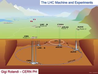
Machine - Experiments Data Exchange Detlef Swoboda LumiWS
LHC systems and project engineers *Installation, control and monitoring of the collision rate monitors (BRANs) is the responsibility of the AB-BI group. LumiWS
Reference Documents • D. Swoboda, LHC Machine And Experiment Date Exchange Systems Implementation EDMS 772011 v.4 • E. Tsesmelis, Data and Signals to be Exchanged between the LHC Machine and Experiments. EDMS 701510 (2006). • Wayne Salter et al., LHC Data Interchange Protocol (DIP) Definition. EDMS 457113. • CERN DIP support web page: http://itcofe.web.cern.ch/itcofe/Services/DIP/welcome.html • LHC Experiment Accelerator Data Exchange Working Group (LEADE). • http://lhc-data-exchange.web.cern.ch/lhc-data-exchange/ • Leade Twiki web page: https://uimon.cern.ch/twiki/bin/view/Leade/WebHome • TTC system web page. http://ttc.web.cern.ch/TTC/intro.html • S. Baron, TTC upgrade project. http://ttc-upgrade.web.cern.ch/ttc-upgrade/Default.htm • Jean-Jaques Savioz. The Beam Synchronous Timing Receiver Interface For The Beam Observation System. EDMS 406137. • R. Schmidt AB/CO, Safe Lhc Parameters Generation And Transmission (SLPT) LHC-CI-ES-0004 rev 0.1 EDMS 810607 • HTTP://LHC-DATA-EXCHANGE.WEB.CERN.CH/LHC-DATA-EXCHANGE/ • D. Macina, W.H. Smith, J. Wenninger. LHC Experiments Beam Interlocking, EDMS 653932 (1995). • B. Todd. CIBU: Realisation of The Beam Interlock System User Interface. • EDMS 762173 • B. Puccio et al., User Interface to the Beam Interlock System, EDMS 636589 • R. Jones. The LHC Beam Position System, Presentation At The Leade Working Group Meeting, 26th March 2002. HTTP://LHC-DATA-EXCHANGE.WEB.CERN.CH/LHC-DATA-EXCHANGE/ • Z. Guzik, R. Jacobsson, Proposal for a Beam Phase and Intensity Monitor for the LHCb Experiment, LHCb 2006 - 055 LumiWS
LHC Data Exchange Concept LumiWS
Data Exchange Key features • Data transmission using the DIM/DIP protocol and a publish/subscribe paradigm. • All data are sent with a UTC time stamp and a data quality indicator. • The amount of data sent will be about 250 kB/sec (~ 100 messages/sec). The typical latency is about one second although some messages will have longer latencies. LumiWS
Machine to experiments • https://twiki.cern.ch/twiki/bin/view/Leade/WebHome LumiWS
Additional GMT data from LHC machine to Experiments https://uimon.cern.ch/twiki/bin/view/Leade/WebHome • The AB-BI group intend to publish some dummy data in DIP from January 2007. • This will enable the DCS team to test their software. • Dummy LHC parameters will be transmitted as of 2Q 2007. LumiWS
Data published by Experiments via the DIP In addition publish information on beam condition (BCM) - (e.g. a number between 1 and 5 where 5 causes a beam dump). LumiWS
Hardware Beam Interlocks • The Beam Interlock System (BIS) of the LHC, the LHC Injection Interlock System, and the SPS Extraction Interlock System. • Each Experiment must provide USER_PERMIT signals that are collected by the BIS through the local Beam Interlock Controller (BIC) modules • Interface between Experiment and BIC is via 19-inch 2U modules (CIBU) modules, which can be connected directly or through patch panels in case the generation of the USER_PERMIT signal is at more than 4 m distance from the interface rack. • Beam Dump Requests • provides a hardware link from a user system to the LHC Beam Dumping system • BIS permits injection into the LHC when all systems connected to it are ready for beam. With beams circulating in the LHC, the system transmits beam dump requests from connected systems to the LHC Beam Dumping System. • Injection Inhibit • Inject inhibit hardware interlock would require major cabling work since the corresponding BIC are located close to the injection regions. The Injection Inhibit interlock, set by the experiments, will therefore be a software signal. • In order to protect experiments from signal transmission failure, due to network problems, a timeout will be applied and the Injection-Permit will be assumed to be false after timeout. • The exact details of this software injection inhibit are still be to be decided but it is likely to be transmitted using DIP. • Limit of Supply • AB-CO group is responsible for cabling from the CIBU/patch panel in Experiment rack to the local BIC modules in the LHC tunnel; they will also provide the necessary CIBU modules. • It is the responsibility of each Experiment to provide the input signals to the CIBU modules. LumiWS
BPTX • Each experiment has a beam position monitor about 150 metres either side of their interaction points. • Each monitor consists of four button electrostatic pickups in order to detect the vertical and horizontal position of the beams. • Information • Relative timing between signals from the BPTXs, on either side of the IP, can be used to establish an approximate location of the interaction point • monitor the phase of the LHC clock locally in order to determine whether the TTC is synchronised with the actual arrival of the bunch. • Signals can also be used to identify the location of the bunch train gaps. • Limit of Supply • cables be installed from each BPTX to rack in Experiment. • LHCb have developed a VME module to read the BPTX signals and automatically calculate timing differences. Details of this module will be presented at the next LEADE meeting. LumiWS
BRAN (Lumino meter) • Neutral particles @ 150 m from IP ~ L. • Numbers between ATLAS/CMS and ALICE/LHCb (~10^4 : 1) • 2 technologies: • ATLAS and CMS fast ionization chamber, from Berkeley lab • ALICE and LHC-B based on solid state polycrystalline Cadmium-Telluride (CdTe) sensors from CSA-LETI Grenoble • Limit of Supply • Published via DIP LumiWS
BST (Beam Synchronous Timing) • The BST uses TTC technology to send messages over channel B of the TTC system. • Limit of Supply • AB-BI group is responsible for sending the BST data to the experiments, via dedicated TTC optical fibres. • Responsibility of the experiments to develop their own hardware in order to read and decode the data. • BOBR receiver card developed by the AB-BI group can be used as interface. • Part of the BST data is also transmitted to experiments via DIM/DIP. LumiWS
GMT (General Machine Timing) • For the safe operation of the LHC and experiments, a number of systems require machine parameters that must be generated and distributed around the LHC. • The Safe LHC Parameters (SLP) are part of the GMT telegram. • The system is designed to generate and distribute these parameters in a highly reliable way. • The interface with experiments is achieved through a dedicated VME crate including timing trigger outputs which is connected to the General Machine Timing (GMT) system. • Values of parameters are supplied as TTL voltage levels on the front connections. • Experiments requiring the 40 MHz clock or a TTL level trigger (for hardwired safety interlocks) will want to install the GMT system. LumiWS
Circulating beam type/ring RF parameters Next injection parameters Safe Beam Parameters Beam energy/ring Beam present flag/ring Safe Beam flag/ring Safe collimator flag Post mortem 40 MHz PLL clock Beam intensity/ring LHC machine mode Fill number Particle type/ring GMT features GMT parameters also included in BST frame: GMT exclusive parameters: LumiWS
GMT safe beam flag • The experiments have requested to get the following signals from the GMT system: • - safe "STABLE BEAM" flag • - safe "MOVABLE DETECTOR IN ALLOWED" flag. This flag is TRUE if either the "STABLE BEAM" mode OR “UNSTABLE BEAM" mode is TRUE. • The flag is set at a high level in the GMT system. • "MOVABLE DETECTOR IN ALLOWED" flag = FALSE will be used to dump the beam • "MOVABLE DETECTOR IN ALLOWED" = TRUE AND "STABLE BEAM" flag = FALSE will be used to retract the movable detectors when necessary. LumiWS
GMT Limit of Supply 1. AB-CO takes responsibility for the installation and maintenance of the GMT distribution for the 4 LHC experiments. Each of these 4 installations will consist of: 1 3U timing reception and fan-our crate 1 VME 21 slot crate 1 PowerPC single Board Computer n x CTR-P or V timing modules, depending on the number of H/W trigger signals the experiments will need Total cost estimate per experiment is about 20 KCHF. 2. Concerning the practical GMT installation work: • Each experiment should send to the AB-CO-FE (M. vanden Eynden) the date at which GMT should be made available, along with a list of the first timing triggers they want to receive (in order for us to know how many CTR-V to install). The AB-CO-FE will then proceed with the GMT infrastructure installation • GMT trigger signals have to be declared in the GMT system (in order to activate the CTR-X outputs). Experiments are invited to contact AB-CO-HT (J.Serrano) in order to define these triggers in the GMT system. • AB-CO responsibility and diagnostic tools stop at the front panel of CTR-x modules. • The local cabling and signal integrity between the CTR-x modules and the experiments electronics remains under their responsibility. • In case experiments would need dedicated timing receiver modules (CTR-x) inside their crates (for decoding of GMT telegram for example), CO would charge them 1000 CHF/each. LumiWS
Trigger Timing & Control (TTC) • The TTC system was designed for LHC experiments and provides for the distribution of synchronous timing, level-1 trigger, and individually addressed control signals, to electronics controllers with the appropriate phase relative to the LHC bunch structure, taking account of the different delays due to particle time-of-flight and signal propagation. • Within each trigger distribution zone, the signals can be broadcasted from a single laser source to several hundred destinations over a passive network composed of a hierarchy of optical tree couplers. • Limit of Supply and Planning • The optical fibres carrying the TTC clock and orbit signals arrive in the dedicated Experiment rack at an optical patch-panel. • Experiments must specify their needs for RF2TTC modules. • TTC group will provide a rented VME crate (from the CERN Electronics Pool) for the TTC interface modules. • Rx/Tx-modules (A & D) validated by AB/RF Production Apr07 • RF2TTC proto-module under test (Dec 06) Production Feb07 • C library under development 1Q07 • Central system installation in summer 2007. • The transmission can then be commissioned in Sept 2007. • Modules are equipped with diagnostics and PH will make these diagnostics "readable" by AB/OP and AB/RF. LumiWS
Conclusions • The implementation of calculating rates and luminosity per bunch is still under discussion but needs to be finalized in the near future. • Cabling between instrumentation and experiment areas is progressing satisfactorily. • Testing and commissioning needs still to be organized. LumiWS