Download
1 / 15
150 likes | 355 Views
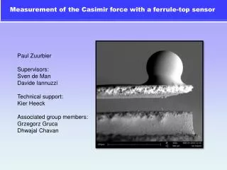
Measurement of the Casimir force with a ferrule-top sensor. Paul Zuurbier Supervisors: Sven de Man Davide Iannuzzi Technical support: Kier Heeck Associated group members: Grzegorz Gruca Dhwajal Chavan. P.C.Caussée L’Album du Marin.

E N D
Measurement of the Casimir force with a ferrule-top sensor Paul Zuurbier Supervisors: Sven de Man Davide Iannuzzi Technical support: Kier Heeck Associated group members: Grzegorz Gruca Dhwajal Chavan
P.C.Caussée L’Album du Marin Two parallel ships are driven to each other by a mysterious attractive force A phenomenon described in 1836 A likely explanation: The two ships act like barriers They are pushed one against the other by the waves outside “the gap”
H.B.G.Casimir (1909-2000) The Casimir effect e.m. wave = harmonic oscillator in vacuum 1948: In the presence of two parallel plates (conductors) The energy Between the Plates is lower d Closely related to van der Waals force
The need of ferrule-top Casimir measurement Increasing interest in studying the Casimir force in various environments, for instance in liquids and with varying temperature. Our group designed and manufactured the ferrule-top sensor, which is versatile, adaptive and cost effective: Measuring Casimir force is difficult, so it is a good benchmark. My job: Test the new sensor by performing the first ferrule-top Casimir force measurement.
solution If too small → F too small Sphere and plate Casimir force Radius ≈ 100 µm d≈ 40 – 200 nm F < ~4000 pN macroscopic objects at microscopic distance diameter ≈ 5000·dmin
Ferrule-top force sensor fabrication Borosilicate ferrule 2.5 x 2.5 x 7.0 mm Laser ablation: 200 x 200 µm ridge 100 µm gap sphere is glued on optical fiber is inserted and fixed with glue hole in cantilever is closed gold layer is sputtered on the sensor
Interferometer Ferrule-top not in use
Table-top setup design Left: Piezo translator with gold plate (varying d) Right: Mechanical translator with sensor + sphere Temperature stabilized Al cylinder Al cover (dust and convection) Dampers Anechoic chamber
problems and solutions: Calibration How does one calibrate a ferrule-top force sensor? We calibrate continuously by applying a well known electrostatic force. We apply an AC voltage to the sphere We measure the signal due to this force at double the frequency We calculate the sensitivity
problems and solutions: Distance How does one measure a distance < 100 nm with ~1 nm accuracy? With an second interferometer we measure Δx. At this stage we know d = Δx + d0, but d0 is unknown. From the electrostatic Coulomb force we get a signal S proportional to 1/d. From this we can fit d0. Δx
problems and solutions: Noise and drift Since k~7 N/m and F<4 nN the cantilever bends only half a nanometer! In this situation the drift of the interferometer intensity is overwhelming. Therefore we vibrate the plate and measure ΔF: Because we are modulating the Casimir force we can use a lock-in amplifier with superior noise suppression (AM).
problems and solutions: Hydrodynamics • Plate vibration airflow hydrodynamic force on sphere. • How does one distinguish between hydrodynamic and Casimir force? The Casimir force depends on d ~ cos(ωt) The hydrodynamic force depends on ~ -sin(ωt) Both signals are 90° out of phase (orthogonal). The signal is measured with a lock-in amplifier and we can get the Casimir force from channel X (in phase) and the hydrodynamic force from channel Y (quadrature).
Final results 40.000 points no free parameters close agreement with theory and earlier experiments conclusion: the sensor is capable of measuring Casimir force, article published NJP