Download
1 / 13
130 likes | 240 Views
This paper presents a novel multiplexed sensing architecture for real-time monitoring of optical fiber arrays using Brillouin shift separation. The method allows for 100% duty cycle monitoring, enhancing precision measurement capabilities for temperature sensing. The system configuration and results of heating and cooling cycles are detailed, showcasing a noise-limited temperature precision of ±0.01°C RMS with a rapid 1-second update time.

E N D
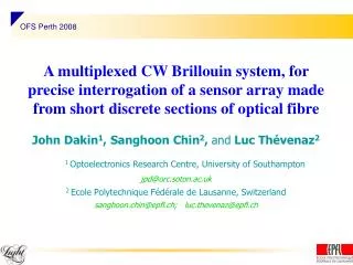
OFS Perth 2008 A multiplexed CW Brillouin system, for precise interrogation of a sensor array made from short discrete sections of optical fibre John Dakin1,Sanghoon Chin2, and Luc Thévenaz2 1 Optoelectronics Research Centre, University of Southampton jpd@orc.soton.ac.uk 2 Ecole Polytechnique Fédérale de Lausanne, Switzerland sanghoon.chin@epfl.ch; luc.thevenaz@epfl.ch
We present, for the first time, a novel multiplexed sensing architecture for real-time monitoring of a small array of optical fibres. Signal separation, is in the frequency domain, rather than the usual time domain, and relies on each fibre having a different Brillouin shift. The ability to monitor with a 100% duty cycle gives enhanced signal to noise ratio, allowing precision measurement. We will show first the basic feasibility of the method, then show how the it may be used for precise temperature measurement. Summary
F3 F2 F1 DFB-LD 1W EDFA VOA Chamber PC nB3 nB2 nB1 nc nc nc Delay Beating notes ESA Det Schematic diagram of basic sensing system The DFB laser pump into the fiber, via a 1W EDFA a circulator, and 3 Brillouin signals return to be mixed with part of the pump wave on a ~12 GHz photo-receiver . (The delay line is used to break coherence of the pump beam, to reduce interference between the pump wave and undesirable pump-wave residues returning from port 3 of circulator) 1
F3 F2 F1 DFB-LD 1W EDFA VOA Chamber PC nB3 nB2 nB1 nc nc nc • Configuration of the cascaded fibers Delay Beating notes ESA Det diameter: 7 cm diameter: 7 cm 50 m of DSF 15 m of DCF 50 m of special fiber with small size of core Schematic diagram of basic sensing system 2
OFS Perth 2008 , being acoustic velocity Theory for Brillouin Shift in Optical Fibres • The Brillouin shift is proportional to the longitudinal acoustic velocity in the glass material, mainly of the fibre core region in which the majority of energy propagates • Fibres of different composition can have significantly different acoustic velocities, as the latter is a function of the density and the Young’s modulus of the glass. • Doping with heavy elements will generally increase the density markedly with respect to pure silica, and many dopants also reduce the Young’s modulus, both parameters therefore tending to reduce the acoustic velocity. • It is therefore relatively easy to select fibres having markedly different Brillouin shifts to suit our multiplexing method!
Measured Brillouin Stokes Spectrum from the 3-fibre array This figure shows three different Brillouin Stokes signals, one from each fibre, as displayed on the electrical spectrum analyzer (ESA). 3
(b) (a) 25 oC 45 oC 65 oC 85 oC 35 oC 55 oC 75 oC Temperature dependence of Stokes Frequency. Frequency change of the Stokes signal, as the temperature of the chamber changes, in steps, from 25 oC to 85 oC. It is clearly seen that only fiber-3 shows a variation, whilst the others scatter light at constant frequency. 4
Linear variation of the Stokes on Temp. This display shows the frequency change of the Stokes as the temperature of the chamber changes from 25 oC to 85 oC. It is clearly seen that only fiber-3 varies, whilst the others stay at the same frequency. 5
n FBG 1 FBG 2 DFB-LD EOM n n Probe Pump 1W EDFA Chamber Delay 1-km SMF VOA F1 F2 F3 Frequency Counter BPF Det n Precision temperature sensor To create a precise temperature sensor, the Stokes scattered light was down-converted, using a modulation sideband of the pump laser as local oscillator, to give a beat signal of order 145 MHz. NOTE: The intermediate-frequency beat signals were then mixed with a 150 MHz local oscillator in a second electrical (i.e. post-detector), down-conversion stage, to give ~ 5 MHz signal for frequency measurement. This 2nd mixing stage will be shown in next slide. 6
Electrical down-conversion Frequency Counter - + RF L.O signal Photoreciever: Bandwidth, 125 MHz High pass filter: Cut-off, 150 MHz Low-pass filter: Cut-off, 15 MHz Detection system, now showing the second (electrical) down-conversion mixing stage 7
Results of heating and cooling cycle The counter frequency was monitored during slow heating and cooling, with a total temperature excursion of ~ 3.5 C. The magnified insert shows the short-term frequency fluctuation was only of ~10 kHz RMS, equivalent to ~ 0.01 C, despite fast (1s) update time. 8
Conclusions • We have conceived and demonstrated a new frequency-division- multiplexed Brillouin sensor system • We have shown that it is possible to get good separation of Brillouin signals by simple selection of commercial fibres • We have shown that the sensor operates with low crosstalk between sensors (NOTE : WE NEED TO DEMONSTRATE THIS NEXT) • We have achieved a noise-limited temperature precision of ~ ± 0.01 C0 RMS, with a fast update time of only 1 second
Acknowledgements Prof John Dakin wishes to thank EPFL for granting him a short visiting professorship All the authors wish to thank Andrew Sansom, of Golledge Electronics, UK, for providing a number of complimentary filter samples at short notice.