Download

1 / 30
320 likes | 543 Views
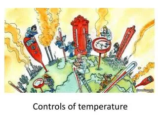
Application of Controls. CAV with Humidity Control. Application of Controls. CAV with Humidity Control CAV AHU dedicated to a special area: clean room textile factory hospital operating theatre computer equipment room

E N D
Application of Controls CAV with Humidity Control
Application of Controls • CAV with Humidity Control • CAV AHU dedicated to a special area: • clean room • textile factory • hospital operating theatre • computer equipment room • Environment requires humidity control as well as temperature control - energy efficiency is not as important
Application of Controls • CAV with Humidity Control T Temperature and humidity sensors may alternatively be placed in return air duct Temperature sensor in space H Humidity sensor in space Return Air Cooling Coil Fan Heater Elements Outdoor Air Chilled Water Valve
Application of Controls • CAV with Humidity Control • The valve is controlled by the humidity sensor to achieve the humidity setpoint. • The heating elements are controlled by the temperature sensor to reheat the air to achieve the temperate setpoint. • This works if outdoor air is used; if pre-treated air is used, cooling request may be greater than dehumidification request and valve is controlled by temperature sensor.
Humidity Temperature Application of Controls CAV with Humidity Control Cooling CoilCommand HeatingCommand D.B. D.B. T S.P. P.B. P.B. S.P. H
Application of Controls Mechanical Controls
Application of Controls Mechanical Controls • FCU Control • A temperature switch in the return air controls the 2 position valve • A separate 3 speed switch is connected to the fan
Application of Controls Mechanical Controls FCU Control A temperature switch in the room controls the 2 position valve The integral 3 speed switch is connected to the fan
Application of Controls Mechanical Controls Condenser Fan As the condenser pressure increases, a fan is started As the pressure continues to rise, a second fan is started FromEvaporator ToCompressor
Application of Controls Mechanical Controls Cooling Tower Fan As the temperature increases, the low speed winding is engaged As the temperature continues to rise, the high speed winding is engaged
Application of Controls Mechanical Controls Cold Room As the temperature increases, the compressors are brought on in sequence Condenser fans controlled based on pressure C1 C2 C3 C4 Condenser Evaporator ColdRoom
Application of Controls Mechanical Controls Compressor Safeties If the condenser pressure is too high or too low, the compressor will be shut down If the lube oil pressure is too low, the compressor will be shut down
Application of Controls Chiller Plant Integration
Application of Controls • Chiller Plant Integration • Single seat user interface • Consolidation of information • Facility wide strategies • Simplify operations / training
Application of Controls • Chiller Plant Integration Local Area Network Operator Workstation (PC) NCU Integrator Dataport Carrier Comfort Network DDC RS232
Application of Controls • Chiller Plant Integration • Chilled Water Setpoint / Control Point • Entering/Leaving Chilled Water Temp. • Entering/Leaving Condenser Water Temp. • Evaporator Refrigerant Temperature and Pressure • Condenser Refrigerant Temperature and Pressure
Application of Controls • Chiller Integration • Discharge Temperature • Bearing Temperature • Motor Winding Temperature • Oil Sump Temperature • Oil Pressure Transducer • etc.... • In brief, anything visible from Control Panel.
Application of Controls Chiller Sequencing
Application of Controls • Chiller Sequencing 1 x 300 TR Chiller
Application of Controls • Chiller Sequencing 3 x 300 TR Chiller 3 Chillers on 2 Chillers on 1 Chiller on
Application of Controls • Chiller Sequencing 3 x 300 TR Chiller +30 HP associatedpumps/fans each 3 Chillers on 2 Chillers on 1 Chiller on
Application of Controls • Chiller Sequencing 3 x 300 TR Chiller +30 HP associatedpumps/fans each Run 2Chillers Run 1 Chiller Run 3 Chillers
Application of Controls • Chiller Sequencing DecreasingLoad Differential to preventshort cycling IncreasingLoad
Application of Controls • Chiller Sequencing • 1. Plot curves for all combinations of chillers including pumps and cooling towers • 2. Take switchover points from graph • 3. Program switchover points with differential • 4. Use run time to choose lead and lag chillers
Application of Controls Chilled Water Reset
Application of Controls • Chilled Water Reset
Application of Controls • Chilled Water Reset
Application of Controls • Chilled Water Reset
Application of Controls • RatioMax. Reset* • AHU 1 8%/Deg 9.1 Deg • AHU 2 6%/Deg 8.5 Deg • AHU 3 5%/Deg 8.0 Deg Chilled Water Reset * Assuming maximum valve position allowed is 85%
Application of Controls • Chilled Water Reset • 1. Record step response of valve position for each AHU to measure system delay and calculate ratio (%/Degree) • 2. Automatically reset chilled water temperature • 3. Look for opportunities to add localized cooling to increase chiller savings