Download
1 / 25
310 likes | 690 Views
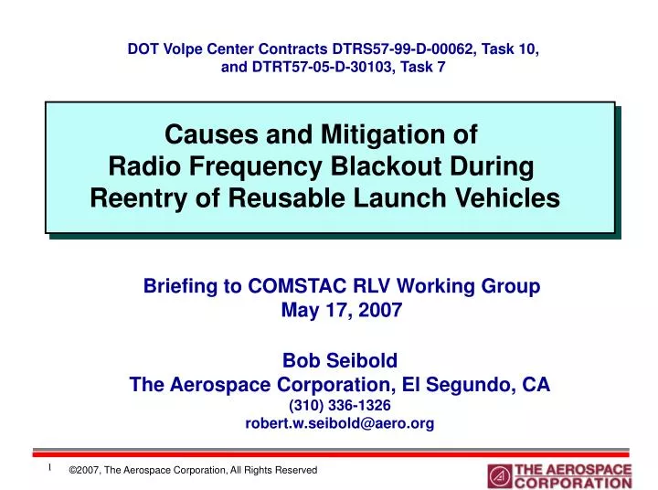
Causes and Mitigation of Radio Frequency Blackout During Reentry of Reusable Launch Vehicles. DOT Volpe Center Contracts DTRS57-99-D-00062, Task 10, and DTRT57-05-D-30103 , Task 7. Briefing to COMSTAC RLV Working Group May 17, 2007. Bob Seibold The Aerospace Corporation, El Segundo, CA

E N D
Causes and Mitigation of Radio Frequency Blackout During Reentry of Reusable Launch Vehicles DOT Volpe Center Contracts DTRS57-99-D-00062, Task 10, and DTRT57-05-D-30103, Task 7 Briefing to COMSTAC RLV Working Group May 17, 2007 Bob Seibold The Aerospace Corporation, El Segundo, CA (310) 336-1326 robert.w.seibold@aero.org
Outline and Acknowledgements • Outline • Backgroud • Approach • Electron Generation Process • Representative Vehicle Classes Analyzed • Plasma Flow Fields • Blackout Trajectories • Mitigation Methodologies • Conclusions • Acknowledgements • FAA/AST Technical Lead: Pradipta Shome • Volpe Center COTR: Ann DiMare • Aerospace Principal Investigators: Dr. Richard Hartunian, Dr. Gordon Stewart • Other Aerospace Contributors: Dr. Thomas Curtiss, Dr. Stephen Fergason • Aerospace Program Manager: Bob Seibold
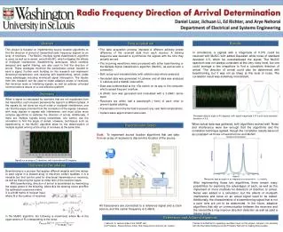
Scope • RF blackout is caused by high electron concentrations in plasma sheaths covering reentering vehicles. These sheaths reflect or attenuate electromagnetic waves. • Vehicles likely to come before AST in the future, that could be affected by blackout, will include orbital RLVs and some suborbital vehicles traveling at high speeds. • Future RLVs could remain in attenuated communication mode during the most critical phase of flight, due to long glide phases for energy management. • Related operation and safety challenges. • Examined causes of blackout for various vehicle classes and potential alleviation methodologies, e.g.: • Aerodynamic shaping • Injection of electrophilic quenchants into plasma layer • Generation of local magnetic fields to create spectral windows through which RF waves can propagate • Study bounded by the following considerations: • Focused on direct RF transmission from vehicles to ground, without use of satellites for indirect transmission • Evaluated both manned and unmanned space vehicles
Approach 1. Defined vehicle classes to be evaluated • Reusable vehicles for future space transportation • Other classes with published flight data relevant to problem 2. Defined ionized flow fields for each vehicle class • Published flight data used where available • Analytic predictions using best state-of-the-art codes, in absence of published flight data 3. Analyzed RF interactions with ionized flow field • Comparisons with analytic predictions and flight data where available 4. Studied mitigation methods • Recommended promising mitigation methods for more detailed assessment 5. Reviewed frequency bands for RF transmission
Representative Vehicle Classes • Blunted conical ballistic reentry vehicles • Sharp-tipped slender conical ballistic reentry vehicles • Unpowered lifting glide vehicle • Space Shuttle concept • Fully reusable 2-stage cargo vehicle for future commercial space transportation • Powered air-breathing lifting vehicle • Blackout unlikely
Ballistic Vehicles and Fully Reusable 2-stage Cargo Vehicle Blunt-tipped RAM C Vehicle and Reentry Flow Characteristics. Reprinted with permission of IEEE [Rybak and Churchill, 1971] RpK K-1 Vehicle. Reprinted with permission of Rocketplane-Kistler Sharp-tipped Ballistic Reentry Vehicle and Reentry Flow Characteristics
Unpowered Glide and Powered Cruise Vehicles Drawing of Space Shuttle Orbiter During Reentry Conditions X-43A Air-breathing Hypersonic Vehicle During Ground Testing Reprinted courtesy of NASA
Sources of Electrons in Plasma Sheaths Plasma sheath created from conversion of vehicle’s kinetic energy, compressing and heating air flow surrounding vehicle: • Temperature of air raised by: • Shock waves at all leading edges and some embedded structures. Conservation of energy equation for direction normal (90º) to vehicle’s velocity vector: (CpT)atm + U2/2 = constant for normal flow across a 1-D shockwave where: Cp = heat capacity, T = temperature, U = velocity of flow • Conversion of viscous stresses due to velocity gradients in flow • As air temperature increases, the following sequence occurs: • Excitement of molecule translation, rotation, and vibration degrees of freedom • Dissociation and ionization • Numerous complex reactions contribute to generation of electrons, beginning with 20% O2 and 80% N2
Electron Generation Process • High reentry temperatures dissociate the oxygen and nitrogen molecules of the air, which triggers complex chemical reactions producing ionization. • All of these reactions need to be accounted for. • 26 example reactions are listed in a backup chart. A representative example is: O2 + N2 NO + NO+ + e- • In an exothermic reaction, molecules collide with enough energy to overcome the activation energy barrier and form an activated complex at a lower energy level. • The released electrons and charged molecules form the plasma sheath, inhibiting communications. • At lower altitudes, the forward and reverse rates become equal, producing chemical equilibrium. At high altitudes, non-equilibrium chemistry prevails.
Definition of Plasma Flow Fields • Blunt, Slender Reentry Vehicles • NASA Radio Attenuation Measurements (RAM) Program Flow Regions About a Conic Shaped Vehicle at 40 km. Reprinted with permission of IEEE [Rybak and Churchill, 1971] Rake of Ion Probes
Definition of Plasma Flow Fields, Con’t. RAM C-II Reentry Trajectory with Onset and End of RF Blackout at 3 Frequencies. Reprinted courtesy of NASA [Grantham, W. L., NASA SP-252, 1970]
Definition of Plasma Flow Fields, Con’t. • Sharp, Slender Reentry Vehicles • Sharp-tipped ballistic RV with shock wave Orange layer (thickness exaggerated) represents location of electrons generated at nose.
Electron Density Decay Along VehicleLength, Sharp-tipped RVs RN = nose radius Clean air peak electron density decay. Reprinted with permission of AIAA [Steiger et al., AIAA 70-220, 1970]
Definition of Plasma Flow Fields, Con’t. • Fully Reusable 2-stage Cargo Vehicle for Future Commercial Space Transportation • RpK K-1 Reprinted with permission of Rocketplane-Kistler
Blackout Trajectories for Two Vehicle Classes 300 Onset of blackout 80 250 Blackout duration, minutes Recovery From blackout Vehicle 200 Shuttle 60 Shuttle 16 RpK OV 1 Altitude – kft Altitude – km RpK OV 150 40 100 20 50 0 0 0 5 10 15 20 25 30 Relative Velocity – kft/sec 0 2 4 6 8 Relative Velocity – km/sec
Definition of Plasma Flow Fields, Con’t. • Space Shuttle • No direct experimental measurement of the ionized flow field on a reentering orbiter • Only known analysis of the ionized flow field was by Dunn and Kang in April 1973 – about 8 years before STS-1 • They modeled the Orbiter as a 20º cone with a 4-ft. radius blunt cone reentering at 20º angle of attack. Despite the fact that the nose radius on the as-built Shuttle is smaller and the entry angle of attack is actually 40º, they concluded that blackout duration would be 15 minutes, close to the actual 16 minutes experienced.
Plasma Flow Profiles for Shuttle Configuration Electron Number Density Distributions in Shock Layer 20º Cone Blunted Delta at 20º ξ = S/RN = ratio of downstream position to hemisphere radius y = distance normal to body surface (abscissa) S = distance along surface of body from nosetip Reprinted courtesy of NASA [Dunn and Kang, NASA CR-2232, April 1973]
Blackout duration, minutes Vehicle Shuttle 16 RpK OV 1 Ram C 0.5 Sharp RV 0 Blackout Trajectories for Four Vehicle Classes 300 Onset of blackout 80 250 Recovery From blackout 200 Shuttle 60 Altitude – km Altitude – kft RpK OV 150 40 100 Ram C 20 50 Sharp RV 0 0 0 5 10 15 20 25 30 Relative Velocity – kft/sec 0 2 4 6 8 Relative Velocity – km/sec
Mitigation Methodologies • Aerodynamic Shaping • Sharp, slender probes/cones containing antenna protruding ahead of shock waves • Issue: Likely to require active cooling of sharp nose region Reprinted with permission of AIAA [Belov, et al., AIAA 99-3739]
Mitigation Methodologies, Con’t. • Injection of Liquids • Injection of electrophilics or other liquids that form droplets that attach electrons and contribute to cooling ahead of antenna on LV • Successfully demonstrated on RAM C-III vehicle with Freon E3 and water injected alternatively. Mass flow rates ranged from <0.1 to 0.45 lb/sec. Complete recovery of RF was achieved. Total mass of liquid required: 14 lbs to erase 32 sec. of blackout for this small vehicle. • Issue: How does the required mass flow of alleviant scale up to a full-size commercial vehicle? • Unpowered lifting-glide vehicle • Powered air-breathing vehicle
Mitigation Methodologies, Con’t. • Application of Magnetic Field • Application of a steady magnetic field in the direction of intended RF propagation • Theory supports concept in principle, e.g., Starkey, et al., 34th AIAA Plasmadynamics and Lasers Conf., June 2003. • NASA experiment reported 20 db reduction with 750 Gauss field applied to laboratory plasma • Japanese team analytical experiment reports 1,500 Gauss penetrates plasma if magnetic field cyclotron frequency equals RF frequency (Whistler mode). Usai, et al., 6th Spacecraft Charging Technology Conf., Sept. 2000, p. 107. • Others estimated 104 Gauss would penetrate air-breathing reentry blacked-out plasma layer • Issue: Whereas current magnetic field strength generation technology may support up to 1,500 Gauss at acceptable weight and volume, the consensus is that achieving 104 Gauss will require advances in superconducting technologies
Other Mitigation Approaches Considered • High Power • Breakdown • Workarounds: pulsed power, bandwidth, adaptive matching, electrophilics • High Frequencies • Atmospheric attenuation • Incompatibility with ground stations/satellites • Frequencies compatible with Automatic Dependent Surveillance - Broadcast Mode (ADS-B) Architecture. 500 MHz lower bound for this task. • Low Frequencies • Antenna size • Incompatibility with ground stations/satellites • Workarounds: trailing wires? • Lasers • Atmospheric attenuation • Not all-weather • Incompatibility with ground stations/satellites • Indirect Communication • Transmit up to satellites • Bent pipe to ground stations
Conclusions • Sharp-tipped RVs experience little or no blackout • Very thin sheath also facilitates other mitigation approaches, e.g., quenchants or magnetic fields, should they be necessary • Blunted conical and lifting-glide vehicles can experience significant blackout • Aerodynamic shaping is most promising approach for mitigating blackout • Investigate sharp, slender probes/cones containing antenna protruding ahead of shock wave • Higher frequencies correlate with decreased blackout • Atmospheric attenuation > ~10 GHz
Chemical Reactions and Rate Coefficients Used in Nonequilibrium Calculations Reprinted courtesy of NASA [Dunn and Kang, NASA CR-2232, April 1973]