Download
1 / 26
260 likes | 385 Views
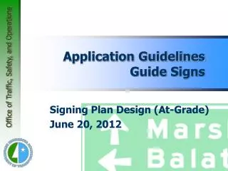
Signing Plan Design - At Grade Intersections TEM Chapter 6-7.0 Application Guidelines - Guide Signing. Application Guidelines - Guide Signing. 6-7.01 Purpose Generally, the only guide sign applications that are discussed in this section are those which:

E N D
Signing Plan Design -At Grade IntersectionsTEM Chapter 6-7.0Application Guidelines - Guide Signing
Application Guidelines - Guide Signing • 6-7.01 Purpose • Generally, the only guide sign applications that are discussed in this section are those which: • 1. Are not specifically addressed in the MN MUTCD, or • 2. Provide additional guidance to that given in the MN MUTCD on application, location and usage of certain types of guide signs, or • 3. Must be addressed because Mn/DOT is charged with developing and implementing design, use and application of certain guide signs in accordance with Minnesota Statutes. Signing Plan Design (At-Grade) Manual
Application Guidelines - Guide Signing • 6-7.02 Conventional Highways • 6-7.02.02 Typical Junction Signing Layouts. • The following typical sign installations should be used as guidelines in establishing sign locations and distances between signs at junctions. The final decision shall be made by the district traffic engineer based on individual intersection geometrics and sound engineering judgement. Signing Plan Design (At-Grade) Manual
Application Guidelines - Guide Signing • 6-7.02 Conventional Highways • 6-7.02.02 Typical Junction Signing Layouts. • 1. "T" intersection (2-lane, 2-way) (See Figure 6.20) • 2. "T" intersection (2-lane, 2-way with 4-lane divided) (See Figure 6.21) • 3. Typical 4-LEG intersection (See Figure 6.22) • 4. Typical intersection with county road (See Figure 6.23) • Review Figures 6.20 - 6.23 (TEM pages 6-92 through 6-95) Signing Plan Design (At-Grade) Manual
Application Guidelines - Guide Signing • 6-7.02 Conventional Highways • 6-7.02.02 Typical Junction Signing Layouts. • 1. "T" intersection (2-lane, 2-way) (See Figure 6.20) • 2. "T" intersection (2-lane, 2-way with 4-lane divided) (See Figure 6.21) • 3. Typical 4-LEG intersection (See Figure 6.22) • 4. Typical intersection with county road (See Figure 6.23) • Review Figures 6.20 - 6.23 Signing Plan Design (At-Grade) Manual
Application Guidelines - Guide Signing • 6-7.02 Conventional Highways • 6-7.02.05 Signal Mast Arm Signing • 1. General Signs are limited in size due to the weight and wind loading factors considered in the design of these structures. The SignCAD program is currently used by Office of Traffic, Security & Operations (OTSO) Signing Unit and district staff in designing guide signs. • Review Figure 6.25 (TEM page 6-97) Signing Plan Design (At-Grade) Manual
Application Guidelines - Guide Signing • 6-7.02 Conventional Highways • 6-7.02.05 Signal Mast Arm Signing • 1. General Signs are limited in size due to the weight and wind loading factors considered in the design of these structures. The SignCAD program is currently used by OTSO Signing Unit and district staff in designing guide signs. • Review Figure 6.25 Signing Plan Design (At-Grade) Manual
Application Guidelines - Guide Signing • 6-7.02 Conventional Highways • 6-7.02.08 Road, Street and 911 Road Name Signing • 2. Urban Areas • If street name signs are to be installed in an urban area (i.e. business, commercial or residential district) "...where parking and/or pedestrian movement is likely to occur or where there are other obstructions to view, the clearance to the bottom of the sign (panel) shall be at least 2.2 m (7 feet)" in accordance with the MN MUTCD, Section 2A-23. • Lateral offset should be a minimum of 0.6 m (2 feet)) from the face of curb in accordance with Section 2A-24. Signing Plan Design (At-Grade) Manual
Application Guidelines - Guide Signing • 6-7.02 Conventional Highways • 6-7.02.08 Road, Street and 911 Road Name Signing • 3. Rural Areas • When the trunk highway intersects a public road, appropriate identification of that public road will be provided on the trunk highway, by Mn/DOT, as follows: • c. Since street name signs are installed on expressways as well as conventional highways, the signs shall be mounted at a height of at least 1.6 m (5 feet), measured from the level of the near edge of the pavement to the bottom of the sign panel(s) in accordance with the MN MUTCD, Section 2A-23. Signing Plan Design (At-Grade) Manual
Application Guidelines - Guide Signing • 6-7.03 Freeways • 6-7.03.05 Expressway At-Grade Intersection Signing • The signing for expressway intersections at-grade is found in Figure 6.30. • Review Figure 6.30 (TEM page 6-102) Signing Plan Design (At-Grade) Manual
Application Guidelines - Guide Signing • 6-7.03 Freeways • 6-7.03.05 Expressway At-Grade Intersection Signing • The signing for expressway intersections at-grade is found in Figure 6.30. • Review Figure 6.30 Signing Plan Design (At-Grade) Manual
Application Guidelines - Guide Signing • 6-7.04 Motorist Services Signing • 6-7.04.01 Wayside Rest - Conventional Highways. • Wayside rests (State owned and maintained facilities only) are those rest stop facilities with limited services located on conventional highways in rural areas. (See Figure 6.32) Correction - Figure 6.33 • Review Figure 6.33 (TEM page 6-108) Signing Plan Design (At-Grade) Manual
Application Guidelines - Guide Signing • 6-7.04 Motorist Services Signing • 6-7.04.01 Wayside Rest - Conventional Highways. • Wayside rests (State owned and maintained facilities only) are those rest stop facilities with limited services located on conventional highways in rural areas. (See Figure 6.32) Correction - Figure 6.33 • Review Figure 6.33 Signing Plan Design (At-Grade) Manual
Application Guidelines - Guide Signing • 6-7.04 Motorist Services Signing • 6-7.04.01 Wayside Rest - Conventional Highways. If the wayside rest is closed for the season, a CLOSED plaque may be installed. • 1. "Wayside Rest" advance sign (D5-X1) shall be installed approximately 800 m (1/2 mile) in advance of the point of turn. When appropriate supplemental signs are used they shall be placed below the D5-X1 or the D5-X2 sign. If the wayside rest has only picnic tables, no supplemental signs shall be used. • 2. "Wayside Rest" with arrow sign (D5-X2) shall be installed approximately 60 m (200 feet) in advance of the point of turn. Signing Plan Design (At-Grade) Manual
Application Guidelines - Guide Signing • 6-7.04 Motorist Services Signing • 6-7.04.02 Resorts and Camping Signs -Conventional Highways. • b. Minimum height to the bottom of the lowest sign panel shall be 2.2 m (7 feet). • c. Where a township road is identified only with a road name sign, the D9-X3 and/or D9-X4 sign panel or panels may be positioned in the same manner as item b above. • d. When a public road is not identified, the D9-X3 and/or D9-X4 signs shall be located approximately 150 m (500 feet) in advance of the intersection. Signing Plan Design (At-Grade) Manual
Application Guidelines - Guide Signing • 6-7.04 Motorist Services Signing • 6-7.04.04 Specific Service Signs (Conventional Highways) • 10. Installation Guidelines • 1) Spacing is to be approximately 90 m (300 feet) from any existing sign to a specific service sign and between specific service signs on two-lane two-way conventional roads. If turn lane signs are in place, specific service signs shall not be installed closer than 60 m (200 feet) in advance of the turn lane signs. In place signs are not to be removed to accommodate specific services signing. Signing Plan Design (At-Grade) Manual
Application Guidelines - Guide Signing • 6-7.04 Motorist Services Signing • 6-7.04.04 Specific Service Signs (Expressways) • 10. Installation Guidelines • 2) Spacing is to be approximately 120 m (400 feet) from any existing sign to a specific service sign and between specific service signs on expressways (non-freeway trunk highways). • b. Normally all specific services signing should be installed on the right side of the roadway. Left side (median) signing (on divided roadways) will be at the discretion of the district. Signing Plan Design (At-Grade) Manual
Application Guidelines - Guide Signing • 6-7.04 Motorist Services Signing • 6-7.04.04 Specific Service Signs (non-freeway only) • 10. Installation Guidelines • e. The maximum number of sign structures per intersection approach will be the number of structures that can be placed within 800 m (one-half mile) of the intersection. • Order of installation: Spacing of signs shall be as indicated in Figure 6.24 (TEM page 6-96). Signing Plan Design (At-Grade) Manual
Application Guidelines - Guide Signing • 6-7.04 Motorist Services Signing • 6-7.04.04 Specific Service Signs (non-freeway only) • 10. Installation Guidelines • e. The maximum number of sign structures per intersection approach will be the number of structures that can be placed within 800 m (one-half mile) of the intersection. • Order of installation: Spacing of signs shall be as indicated in Figure 6.24. Signing Plan Design (At-Grade) Manual
Application Guidelines - Guide Signing • 6-7.04 Motorist Services Signing • 6-7.04.08 Signing for Hospital Motorist Services • On expressways in urban metropolitan areas, the HOSPITAL sign (E10-8) shall be installed in advance of the trunk highway interchange/intersection nearest the hospital. Signing Plan Design (At-Grade) Manual
Application Guidelines - Guide Signing • 6-7.04 Motorist Services Signing • 6-7.04.08 Signing for Hospital Motorist Services • On conventional highways the Hospital symbol sign (D9-2B) shall be installed on the ground in advance of, or on a traffic signal mast arm at the intersection with the road leading to the hospital. Signing Plan Design (At-Grade) Manual
Application Guidelines - Guide Signing • 6-7.04 Motorist Services Signing • 6-7.04.08 Signing for Hospital Motorist Services • See Mn/DOT Memo, TEO Signing Committee Topic #229 (included in Appendix) • The distance to a hospital located 2 miles or more from a trunk highway intersection shall be shown in one mile increments on the hospital service sign. • E10-4 sign shown below Signing Plan Design (At-Grade) Manual
Application Guidelines - Guide Signing • 6-7.04 Motorist Services Signing • 6-7.04.08 Signing for Hospital Motorist Services • See Mn/DOT Memo, TEO Signing Committee Topic #229 (included in Appendix) • Any trailblazing signing (D9-2a) on trunk highways shall display either the number of blocks or miles, in one mile increments, to the hospital Signing Plan Design (At-Grade) Manual
Application Guidelines - Guide Signing • 6-7.04 Motorist Services Signing • 6-7.04.08 Signing for Hospital Motorist Services • See Mn/DOT Memo, TEO Signing Committee Topic #229 (included in Appendix) • Replace existing signs through normal attrition to conform with these recommendations. Signing Plan Design (At-Grade) Manual
Application Guidelines - Guide Signing • 6-7.09 Reference Post System • The zero reference point should begin at the south or west State line, and at the south or west junctions where routes begin. • When a reference post marker cannot be erected in its correct location, it may be moved up to 15 m (50 feet) in either direction. If it cannot be placed within 15 m (50 feet) of its correct location, it should be omitted. Signing Plan Design (At-Grade) Manual
Application Guidelines - Guide Signing • 6-7.09 Reference Post System • Further information about the Reference Post System can be found in Chapter 13, Section 13- 4.09. • For the design and size of reference post markers refer to the MN MUTCD. Signing Plan Design (At-Grade) Manual