Cryogenic development in KAGRA
310 likes | 329 Views
This study presents the performance test results of the KAGRA cooling system (cryostat and cryo duct) before their installation at the KAGRA site. The test was conducted to evaluate the cooling efficiency and radiation propagation in the cryostats and cryo ducts. The results show that the initial cooling time and radiation absorption are within the expected range. The test at the KAGRA site is ongoing to assess the system's performance.

Cryogenic development in KAGRA
E N D
Presentation Transcript
Cryogenicdevelopment in KAGRA Kazuhiro Yamamoto on behalf of the KAGRA collaboration Department of physics, Faculty of Science, University of Toyama Gravitational Wave Advanced Detector Workshop @Reef view hotel, Hamilton island, Queendland, Australia 10 May 2017 1 1 1 1
Abstract We tested performance of KAGRA cooling system (cryostat and so on) before they were installed at KAGRA site. Here, result of performance test at KAGRA site is introduced.
Contents • Outlines • Test before installation at site • Test at KAGRA site • Discussion and summary
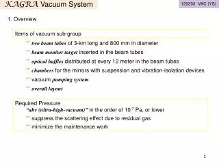
1. Outlines Two unique key features of KAGRA Cooled mirror to reduce thermal noise Underground site with small seismic motion 3km Y end 3km X front X end Y front Kamioka mine (Underground site) Atotsu Center Laser 4 4 4 4 4 4 4 4 4
Outlines Main mirror parts 14m Beam duct
Outlines Main mirror parts We have already installed at site ! Vibration isolation system at room temperature Cryo duct in order to terminate 300K radiation 14m Beam duct Cryostatwith four cryocoolers
1. Outlines Stainless steel t=20mm Diameter 2.4 m Height ~4.3 m M ~ 12 ton Cold Mass: 8K shield ~455 kg 80 K shield ~590 kg Seismic Attenuation System (SAS) Cryogenic Payload 4.3 m Sapphire Mirror (-alumina crystal) View Ports Radiation Shields Duct Shield Main Laser Beam Cryocoolers Pulse tube, 60Hz 0.9 W at 4K (2nd) 36 W at 50K (1st) Four Cryocooler Units 2.6m S.Koike Heat links (soft aluminum) are necessary to cool down cryo payload
1. Outlines Cryo duct Mirror Baffle to terminate radiation propagation effectively
1. Outlines Here, Kazuhiro Yamamoto explains cryostat and cryo duct performance check (and vibration of shield at site in his next talk). Cryostat includes most important parts, cryogenic payload with sapphire mirrors. Takafumi Ushiba shows details of cryogenic payload in next talk. Koki Okutomi presents control system of vibration isolation system with cryo payload in tomorrow morning session.
1. Outlines KAGRA schedule bKAGRA phase I (until March 2018) : CryogenicMichelson interferometer bKAGRA phase II (until March 2019) : CryogenicFabry Perot Michelson interferometer Roughly speaking, Cryostats at both end stations must be ready soon. Cryostats in center room will be ready in next one year.
2. Test before installation at site All cryostats and cryo ducts have already been installed at KAGAR site. Performance test before installation at site Cryostat : Cooling test of radiation shields for all four cryostat (Toshiba) Yusuke Sakakibara et al., Classical and Quantum Gravity 31 (2014) 224003. Cryoduct : Cooling test for all eight cryo ducts Measurement of 300K radiation propagation in cryo duct(Torisha) Yusuke Sakakibara et al., Classical and Quantum Gravity 32 (2015) 155001.
2. Test before installation at site Result before installation at site Initial cooling of radiation shield is about two weeks. This is comparable with our expectation. After cooling down, temperature is 7 K - 10K.
2. Test before installation at site Simple evaluation for initial cooling time KAGRA : Total mass of inner radiation shield is about 700 kg. C. Tokoku et al., CEC/ICMC2013, 2EPoE1-03, Anchorage, USA (2013). Typical specific heat : 1000 J/Kg/K at 300K Dulong-Petit law Since power of heat extraction of cryocoolers is 100W, the cooling time is 14 days.
2. Test before installation at site Result before installation at site Propagation of 300K radiation in cryo duct Yusuke Sakakibara et al., Classical and Quantum Gravity 32 (2015) 155001. Power transmitted by cryo duct Incident power to cryo duct Cryo duct absorbs 300K radiation enough.
2. Test before installation at site Then all of cryostats and cryo duct were transported to and assembled at KAGRA site. KAGRA site Cryostat Cryo duct
3. Test at KAGRA site All cryostats and cryo ducts were assembled at KAGRA site. Now we are investigating their performance. What are differences test at KAGRA site from test at Toshiba and Torisha ? (1)We NEVER checked performance of combined cryostat and cryo ducts. (2)Radiation shield of cryostat was perfectly closed at Toshiba. Now it is opened (otherwise, laser beam can not achieve mirror !).
3. Test at KAGRA site Cooling test of cryostats and cyroducts are in progress at site. 3km Y end (Done) 3km X front (Done) X end (Done) Y front (Not yet) Atotsu Center 17 17 17 17 17 17 17 17 17
Cooling test (main radiation shield) at X-end (2017.Feb.6~Mar.13) Feb. 6 Operation start Toshiba KAGRAsite Initial cooling time is comparable with that at Toshiba.
Temperature of main cryostat at X-end @2017 Feb. 22 ~82 K at the top of the 80 K outer shield 13.2 K at the side of 8 K inner shield 47~56 K @ 1st cold stage of Cryo-cooler 6.1 & 6.8 K @ cryo payload system 12.5 K @ shield sysytem 3.9 & 5.7 K @ cryo payload system 10 & 12 K @ 8 K shield
Temperature of main cryostat at X-front @2017 Mar. 13 ~72 K at the top of the 80 K outer shield 11.3 K at the side of 8 K inner shield 42~53 K @ 1st cold stage of Cryo-cooler 6.0 K @ cryo payload system ~11.2 K @ shield system 4.3 & 4.5 K @ cryo payload system 8.4 & 9.6 K @ 8 K shield
Temperature of main cryostat at X-end @2017 Feb. 22 Lowest temperature is enough low but slightly higher than that at Toshiba. It could be extra heat load through cryo duct (a few W ?). It looks larger than our expectation. We are considering what happens exactly ….
Result of cooling test of cryo ducts Bad! BRT Y-end-BRT EYC Y-end-ARM KAGRA Cryogenics Configuration Good! EYA Y-arm 3 km We checked six cryo ducts. Two of them are OK, but … IYA ? Y-front-ARM IYC ? Y-front-BS IXC EXC X-arm EXA IXA BRT Good! Bad! Bad! 3 km X-front-BS X-front-ARM X-end-ARM X-end-BRT BS Bad!
Temperature distribution of the cryo-duct In case of good result! TX-BS-4=82.1 K TY-ARM-4=82.6 K TX-BS-1=75.9 K TY-ARM-1=70.0 K TX-BS-3=81.1 K TY-ARM-3=81.0 K TX-BS-2=76.1 K TY-ARM-2=75.0 K Upper side: X-front BS side Lower side: Y-end arm side We confirmed that two of six cryo-ducts satisfy requirement. One is Y-end arm side, the other one is X-front BS side.
Temperature distribution in 80 Kcryo-coolers In case of good result! TX-BS-1=45.6 K TY-ARM-1=43.5 K Vibration reduction system TX-BS-3=60.6 K TARM-3=59.8 K TX-BS-2=53.9 K TARM-2=56.3 K 5N Al heat conductor
Temperature distribution of the cryo-duct In case of bad result! TX-ARM-4=96.8 K TY-BRT-4=112.8 K Contact to crycooler (Unexpected contact to vacuum chamber ?) TX-ARM-1=90.2 K TY-BRT-1=85.0 K TX-ARM-3=96.0 K TY-BRT-3=108.1 K TX-ARM-2=90.9 K TY-BRT-2=94.9 K Upper side: X-front arm side Lower side: Y-end BRT side We found larger temperature gradient in other four cryo-ducts. Now, we are trying to fix of malfunctions and must check two cryo-ducts at Y-front.
Temperature distribution in 80 Kcryo-coolers In case of bad result! TX-ARM-1=47.9 K TY-ARM-1=48.3 K Vibration reduction system TX-ARM-3=69.1 K TY-ARM-3=67.6 K TX-ARM-2=59.7 K TY-ARM-2=58.3 K 5N Al heat conductor We found larger temperature gradient in other four cryo-ducts. Now, we are trying to fix of malfunctions and must check two cryo-ducts at Y-front.
4. Discussion and summary Initial cooling time at site is comparable with that before installation at site. We found extra heat load on shield of cryostat and cryo ducts. We have some ideas, but we must check. We proceed with cooling test at Y front. However, we expect that they do not matter for bKAGRA phase I. Cryostats and cryo duct can be prepared for phase I ! Nobuhiro Kimura leads installation and check at site. His expertise (cryogenic system in particle accelerators) contribute KAGRA absolutely.
2. Before installation at site Yusuke Sakakibara (ICRR at that time) conducted experiment. Y. Sakakibara et al., Classical and Quantum Gravity 31(2014)224003. 29 29 29 29 29 29 29 29 29
Pressure after leak test 1. Introduction X-end Cryostat 7th of Oct 8:47 BRT: 1.9 x 10⁻⁴ Pa EXA: 2.5 x 10⁻⁴ Pa Cryocooler test operation Y-end Cryostat BRT: 2.1 x 10⁻⁴ Pa、EYA: 2.5 x 10⁻⁴ Pa This pressure is enough low for cooling test. But (small) leakage must be fixed after cooling test, We know where it is and new O-ring has already been ordered. 30 30 30 30 30 30 30 30 30 30
Temperature distribution2016 Nov.28 4K bar for Shield 4K side 80K side 80K bottom 4K bar for Pay 31 31 31 31 31 31 31 31 31