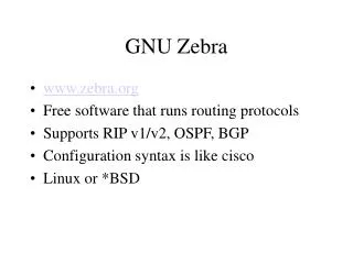
GNU Radio
400 likes | 615 Views
GNU Radio. Chen Zhifeng Chen Ke-Yu Electrical and Computer Engineering University of Florida. Outline. Why GNU Radio? Extensive knowledge involved What is implemented currently? Library Architecture D evelopment e nvironment Development Boards Current Issues What is next?.

GNU Radio
E N D
Presentation Transcript
GNU Radio Chen Zhifeng Chen Ke-Yu Electrical and Computer Engineering University of Florida
Outline • Why GNU Radio? • Extensive knowledge involved • What is implemented currently? • Library • Architecture • Development environment • Development Boards • Current Issues • What is next?
Why GNU Radio? • Almost free! • All the software are free (Python and C++ source code/linux environment) • In most condition, no need expensive RF test machine! • No need to purchase development and emulation tools • Only a development board needed (Universal Software Radio Peripheral) • Flexible • Software: • reconfigurable for many other modulation methods for both standardize radio or self-defined radio • it is possible to improve the quality of the received signal by utilizing, in software, certain mathematical algorithms • Hardware: • Rx and Tx are selectable • Intermediate frequency is controllable • Best choice for research use and radio amateur
Extensive knowledge involved • Software and environment: • Python/Numeric python library/wxPython • C++/boost C++ libraties • Linux environment and lots of support packages: FFTW/cppunit/SWIG/SDCC/ • GNU Radio architecture • Communications and RF: • DSP • Digital communications • Wireless communications theory • FPGA and Assemble language may be used
What is implementedcurrently • Base System • Provides the runtime and various signal processing primitives • Hardware Support • Universal Software Radio Peripheral (USRP) • Audio Device Support • ALSA (Advanced Linux Sound Architecture) • OSS (Open Sound System) • Graphics Support • wxPython based GUI • SDL video library • General Signal Processing • Specialty Application Areas
Library • Communication related implementation • AM demodulation • Differential BPSK / QPSK • GMSK modulation / demodulation • Narrow band FM transmitter / receiver • Wide band FM transmitter & broadcast FM receiver
Library (cont.) • GNU radio utilities • CRC generator • Socket setup (TCP / UDP) • Compute frequency response of a digital filter • Control National IMX2306 & SDR-1000 frequency synthesizer • Some utilities • Convert unsigned mask into signed integer • Gcd, Lcm, Log2 • Return input ‘x’ that is reverse order
Library (cont.) • GUI examples • Provide window application for different usage • FFT sink test • wxPython EditBox, Slider • Drawing • Waterfall sink test • Oscilloscope Test Application
Library (cont.) • pager • Create USRP source object supplying complex floats • Flex pager protocol demodulation block
Hardware Software Architecture – overall
DAC RF Front end USB FPGA Receiver User-defined Code ADC RF Front end USB FPGA Architecture – Hardware Sender User-defined Code PC USRP (mother board)
DAC RF Front end USB FPGA Architecture – Hardware Support USB2.0/At this stage, USB 1.x is not supported at all • Support 32MB/sec across the USB. • All samples sent over the USB interface are in 16-bit signed integers in IQ format, • 16-bit I and 16-bit Q data (complex), resulting in 8M complex samples/sec • across the USB. User-defined Code
DAC RF Front end USB FPGA Architecture – Hardware • Includes digital down converters (DDC) implemented with cascaded integrator-comb (CIC) filters. DDC • Down converts the signal from the IF band to the base band. • Decimates the signal so that the data rate can be adapted by the USB 2.0 and is reasonable for the computers' computing capability. • Digital up converters (DUCs) on the transmit side are actually contained in the AD9862 CODEC chips, not in the FPGA. • The only transmit signal processing blocks in the FPGA are the interpolators. User-defined Code
DAC RF Front end USB FPGA Architecture – Hardware • 4 high-speed 14-bit DA converters, DAC clock frequency is 128 MS/s (stay below about 50MHz or so to make filtering easier.) • 4 high-speed 12-bit AD converters, sampling rate is 64M samples per second. User-defined Code
DAC RF Front end USB FPGA Architecture – Hardware • One mother board support up to four daughter boards. • 2. Several kinds of daughter boards available User-defined Code
DAC RF Front end USB FPGA Architecture – Software Sender • GNU radio has provided some useful APIs • What we are interested in at this time is how to use the existing modules that has been provided in GNU radio project to communicate between two end systems User-defined Code PC
Architecture – Software • How these modules co-work? • C++ • Performance-critical modules • Python • Glue to connect modules • Non performance-critical modules
V1 C++ V3 C++ V2 Sink C++ Source Architecture – Software V1 At python level, what we need to do is always just to draw a diagram showing the signal flow from the source to the sink in our mind. C++ V3 C++ V2 C++
Explorer of Project and Class members Code editor Interpreter & debug window Development environment • SPE (Stani’s Python Editor) • Free • Lack of powerful debug tool (breakpoint)
Code editor Explorer of Project and Class members Interpreter Debug information Development environment (cont.) • Wingware • More powerful • For personal version, the license fee to two stations are $60
USRP Motherboard • Four 64 MS/s 12-bit analog to digital Converters • Four 128 MS/s 14-bit digital to analog Converters • Four digital downconverters with programmable decimation rates • Two digital upconverters with programmable interpolation rates • High-speed USB 2.0 interface (480 Mb/s) • Capable of processing signals up to 16 MHz wide • Modular architecture supports wide variety of RF daughterboards • Auxiliary analog and digital I/O support complex radio controls such as RSSI and AGC • Fully coherent multi-channel systems (MIMO capable)
BasicTX2 MHz to 200 MHz Transmitter • designed for use with external RF frontends as an intermediate frequency (IF) interface. • DAC outputs are directly transformer-coupled to SMA connectors (50Ω impedance) • direct access to all of the signals on the daughterboard interface
BasicRX2 MHz to 300+ MHz Receiver • designed for use with external RF frontends as an intermediate frequency (IF) interface. • ADC inputs are directly transformer-coupled to SMA connectors (50Ω impedance) • direct access to all of the signals on the daughterboard interface
LFTXDC-30 MHz Transmitter • very similar to the BasicTX and BasicRX, respectively, with 2 main differences • Use differential amplifiers instead of transformers, their frequency response extends down to DC. • have 30 MHz low pass filters for antialiasing.
LFRXDC-30 MHz Receiver • very similar to the BasicTX and BasicRX, respectively, with 2 main differences • Use differential amplifiers instead of transformers, their frequency response extends down to DC. • have 30 MHz low pass filters for antialiasing.
TVRX50 MHz to 870 MHz Receiver • a complete VHF and UHF receiver system based on a TV tuner module • can receive a 6 MHz wide block of spectrum from anywhere in the 50-860 MHz range. • All tuning and AGC functions can be controlled from software. • Note: The TVRX is the only daughterboard which is NOT MIMO capable. A MIMO capable version is expected in Q1 2007.
DBSRX800 MHz to 2.4 GHz Receiver • a complete receiver system for 800 MHz to 2.4 GHz with a 3-5 dB noise figure. • features a software controllable channel filter as narrow as 1 MHz, or as wide as 60 MHz. • MIMO capable, and can power an active antenna via the coax. Note: The DBSRX is NOT guaranteed to cover the 2.4-2.48 GHz ISM band.
RFX400400-500 MHz Transceiver • 100+mW output (20dBm) • ideal for UHF TV, public safety and land-mobile communications, low-power unlicensed devices (like key-fobs), wireless sensor networks (motes), and amateur radio. • minor modifications to the board can move the frequency range to anywhere from 200 MHz to 800 MHz
RFX900800-1000MHz Transceiver • 200+mW output (23dBm) • with a 902-928 MHz ISM-band filter installed for filtering strong out-of-band signals (like pagers). • The filter can easily be bypassed to allow usage over the full frequency range, enabling use with cellular, paging, motes, and two-way radio, in addition to the ISM band.
RFX12001150 MHz - 1450 MHz Transceiver • 200+mW output (23dBm) • Coverage of navigation, satellite, and amateur bands.
RFX18001.5-2.1 GHz Transceiver • 100+mW output(20dBm) • Coverage of DECT, US-DECT, and PCS (including unlicensed) frequencies.
RFX24002.3-2.9 GHz Transceiver • 50mW output (17dBm) • with a bandpass filter around the ISM band (2400-2483 MHz). • The filter can be easily bypassed, allowing for coverage of the full frequency range.
Demo Modulation Hard Disk JPEG Encoder Socket Hard Disk Demodulation Socket
Gray code Encoder Differential Encoder Real to Complex Bit to Byte Gray code Decoder Differential Decoder Real to Complex Byte to Bit Demo (cont.) Modulation Demodulation
Current issues • Need a USRP + Microtune 4937 • Need a python IDE • A long way to be commercialized • High performance CPU requirement • The software is still under development
What is next?--possible applications and issues • The clock recovery block doesn’t work in the DBPSK modulation • Add more functions, such as DQPSK, FSK… into our demo • We may test the transmission by actual wireless connection, since receiver doesn’t ensure correct demodulation, for example, carrier tracking, clock recovery, we may need to add: • cyclic redundancy check (CRC) • Retransmission control (ARQ) • Based on what we have done, we may deploy a research-oriented project next