Download

1 / 55
560 likes | 624 Views
This model analyzes bank stability incorporating toe-erosion, hydraulic erosion, vegetation effects, and more. Follow the step-by-step guide to assess water table depth impacts.

E N D
Bank-Stability and Toe-Erosion Model Andrew Simon, Robert Thomas, Andrea Curini and Natasha Bankhead USDA-ARS National Sedimentation Laboratory, Oxford, MS
2-D wedge- and • cantilever-failures • Tension cracks • Search routine for failures • Hydraulic toe erosion • Complex bank geometries • Positive and negative pore-water pressures • Confining pressure from flow • Incorporates layers of different strength • Vegetation effects: RipRoot • Inputs: gs, c’, f’, fb , h, uw, • k, tc Bank-Stability Model Version 5.0 shear surface Tensiometers (pore pressure) Confining pressure WATER LEVEL, M
Model Structure • Introduction page: provides general background • Technical Background page: provides equations for stability analysis including positive and negative pore-water pressures, effects of vegetation, and the toe-erosion algorithm. • Model Use and FAQ page: provides methodology for application of model features including hints for working with bank geometry, selecting the shear surface, soil layers, pore-water pressure/water table, vegetation, and the toe-erosion algorithm.
Model Structure (cont’d) • Input Geometry page: Enter coordinates for bank profile, soil layer thickness, and flow parameters.. • Bank Material page: Enter bank-material properties (geotechnical and hydraulic) • Bank Vegetation and Protection page: Run root reinforcement (RipRoot) model and to input default values of bank and toe protection. • Bank Model Output page: Enter water-table depth and obtain results.
Model Structure (cont’d) • Toe Model Output page: Run shear stress macro and obtain toe-erosion results. • Unit Converter page: Imperial (English) to metric units
Modeling Steps • Model the current bank profile by first evaluating the effect of hydraulic erosion at the bank toe. • Take the resulting new profile and run this in the bank- stability model to see if the eroded bank is stable. • Investigate the effects of water-table elevation, stage, tension cracks, vegetation, and toe protection.
Operational Steps • Open Excel file “BSTEM-5.0” • Click on “Enable Macros”…to “Introduction” sheet
Operational Steps • Open Excel file “BSTEM-5.0” • Click on “Enable Macros”…to “Introduction” sheet • Click on “Input Geometry” sheet
Input Geometry Sheet Run Bank Geometry Macro
Operational Steps • Open Excel file “BSTEM-5.0” • Click on “Enable Macros”…to “Introduction” sheet • Click on “Input Geometry” sheet • Select EITHER Option A or Option B forbank geometry and input geometry data. For this first example select Option B.
Input Geometry Sheet Run Bank Geometry Macro National Sedimentation Laboratory
Starting with Option B • Select: Option B • 5m high bank • 85 degree angle • 1m toe length • 25 degree toe angle If you don’t know failure-plane angle, search routine will solve for it.
Operational Steps • Open Excel file “BSTEM-5.0” • Click on “Enable Macros”…to “Introduction” sheet • Click on “Input Geometry” sheet • Select EITHER Option A or Option B to input bank geometry • Enter Bank-layer Thickness
Enter Bank Layer Thickness Run Bank Geometry Macro
Enter Bank Layer Thickness: Detail For this example, enter 1m thicknesses for all five layers Layer 5 should (but does not have to) end at or below the base of the bank toe. Therefore, the basal elevation of layer 5 should be equal to or less than the elevation of point V (base of bank toe) if Option A is selected or 0 (zero) if Option B is selected.
Operational Steps • Open Excel file “BSTEM-5.0” • Click on “Enable Macros”…to “Introduction” sheet • Click on “Input Geometry” sheet • Select EITHER Option A or Option B to input bank geometry • Enter bank-layer thickness • Enter channel and flow parameters, and check cross section inputs: a. View Geometry b. Bank Geometry Macro
Channel and Flow Parameters: Detail Input the above values for this example
Check Geometry and Flow Level • Model will direct you to the Bank Material sheet • Click on Bank Model Output sheet
Operational Steps • Open Excel file “BSTEM-5.0” • Click on “Enable Macros”…to “Introduction” sheet • Click on “Input Geometry” sheet • Select EITHER Option A or Option B to input bank geometry • Enter Bank-layer Thickness • Enter channel and flow parameters • Enter Bank-material Properties: Click on “Bank Material” sheet
Select Bank Materials by Layer Select bank materials by layer from drop down boxes. For this case: Layer 1 = Moderate soft clay, Layer 2 = Moderate soft clay, Layer 3 = Moderate silt, Layer 4 = Erodible silt, Layer 5 = Moderate silt, Bank Toe Material = Own data
Selecting Bank Materials Input value (2.00) and hit enter Enter values (2.00 and 0.071)
Operational Steps • Open Excel file “BSTEM-5.0” • Click on “Enable Macros”…to “Introduction” sheet • Click on “Input Geometry” sheet • Select EITHER Option A or Option B to input bank geometry • Enter Bank-layer Thickness • Enter channel and flow parameters • Enter Bank-material Properties: Click on “Bank Material” sheet • Select “Toe Model Output” sheet and Click on “Run Toe-Erosion Model”
Results of Toe-Erosion Model Click this button to export eroded profile to Option A in “Input Geometry” worksheet
Operational Steps • Open Excel file “BSTEM-5.0” • Click on “Enable Macros”…to “Introduction” sheet • Click on “Input Geometry” sheet • Select EITHER Option A or Option B to input bank geometry • Enter Bank-layer Thickness • Enter channel and flow parameters • Enter Bank-material Properties: Click on “Bank Material” sheet • Select “Toe Model Output” sheet and Click on “Run Toe-Erosion Model” • Export Coordinates to Model (Returned to “Input Geometry” sheet)
Profile Exported into Option A(Model Directs you to “Input Geometry” sheet) Check profile (View Geometry) and select top of bank toe For this case select Point Q Either: (1) Select shear emergence elevation and shear angle or (2) leave blank for search routine
Operational Steps • Open Excel file “BSTEM-5.0” • Click on “Enable Macros”…to “Introduction” sheet • Click on “Input Geometry” sheet • Select EITHER Option A or Option B to input bank geometry • Enter Bank-layer Thickness • Enter channel and flow parameters • Enter Bank-material Properties: Click on “Bank Material” sheet • Select “Toe Model Output” sheet and Click on “Run Toe-Erosion Model” • Export Coordinates to Model (Returned to “Input Geometry” sheet) • Run “Bank Geometry Macro” and Click on “Bank Model Output” sheet; Set water-table depth and Click “Run Bank Stability Model”
Data for Pore-Water Pressure In “Bank Model Output” worksheet In this case select option to use water table depth, and enter a value of 3.0m below the bank top Or
Bank Model Output: No Tension Crack Set water-table depth to 3.0 m Bank is Unstable Fs < 1.0 Click “Run Bank-Stability Model”
Bank Model Output: Specific Results Failure dimensions (loading) Failure plane from search routine Save your file under a different name
Operational Steps • Open Excel file “BSTEM-5.0” • Click on “Enable Macros”…to “Introduction” sheet • Click on “Input Geometry” sheet • Select EITHER Option A or Option B to input bank geometry • Enter Bank-layer Thickness • Enter channel and flow parameters • Enter Bank-material Properties: Click on “Bank Material” sheet • Select “Toe Model Output” sheet and Click on “Run Toe-Erosion Model” • Export Coordinates to Model (Returned to “Input Geometry” sheet) • Run “Bank Geometry Macro” and Click on “Bank Model Output” sheet; Set water-table depth and Click “Run Bank Stability Model” • Save file under different name
How can you make this bank more stable or more unstable? Try experimenting with the following parameters to get a feel for the model: • Water surface elevation (Input Geometry Sheet) • Shear angle (Input Geometry Sheet) • Water table height (Bank Model Output sheet) • Bank material types (Bank Model Output sheet) We’ll work with the effects of vegetation later…
Operational Steps • Open Excel file “BSTEM-5.0” • Click on “Enable Macros”…to “Introduction” sheet • Click on “Input Geometry” sheet • Select EITHER Option A or Option B to input bank geometry • Enter Bank-layer Thickness • Enter channel and flow parameters • Enter Bank-material Properties: Click on “Bank Material” sheet • Select “Toe Model Output” sheet and Click on “Run Toe-Erosion Model” • Export Coordinates to Model (Returned to “Input Geometry” sheet) • Run “Bank Geometry Macro” and Click on “Bank Model Output” sheet; Set water-table depth and Click “Run Bank Stability Model” • Save file under different name • Open file and Click on “Bank Vegetation and Protection” sheet
Incorporating Vegetation Effects and other Protection Root Reinforcement: RipRoot (from measured data) Bank and Toe Protection (from literature values)
Operational Steps • Open Excel file “BSTEM-5.0” • Click on “Enable Macros”…to “Introduction” sheet • Click on “Input Geometry” sheet • Select EITHER Option A or Option B to input bank geometry • Enter Bank-layer Thickness • Enter channel and flow parameters • Enter Bank-material Properties: Click on “Bank Material” sheet • Select “Toe Model Output” sheet and Click on “Run Toe-Erosion Model” • Export Coordinates to Model (Returned to “Input Geometry” sheet) • Run “Bank Geometry Macro” and Click on “Bank Model Output” sheet; Set water-table depth and Click “Run Bank Stability Model” • Save file under different name • Open file and Click on “Bank Vegetation and Protection” sheet • Click “Run Root-Reinforcement Model”
Root Reinforcement using RipRoot 1. Select “Meadow, Wet” 2. Enter age and percent contribution to stand 3. Click when finished Simple Case: 1 species
Operational Steps • Open Excel file “BSTEM-5.0” • Click on “Enable Macros”…to “Introduction” sheet • Click on “Input Geometry” sheet • Select EITHER Option A or Option B to input bank geometry • Enter Bank-layer Thickness • Enter channel and flow parameters • Enter Bank-material Properties: Click on “Bank Material” sheet • Select “Toe Model Output” sheet and Click on “Run Toe-Erosion Model” • Export Coordinates to Model (Returned to “Input Geometry” sheet) • Run “Bank Geometry Macro” and Click on “Bank Model Output” sheet; Set water-table depth and Click “Run Bank Stability Model” • Save file under different name • Open file and Click on “Bank Vegetation and Protection” sheet • Click “Run Root-Reinforcement Model” • Return to “Bank Model Output” sheet
Still Unstable with Vegetation Revised strength and Fscalculated automatically
Conditionally Stable with Lower Water Table Change water-table depth to 3.5 m Revised pore-water pressures and Fscalculated automatically
Further Simulations…Tension Cracks 1. Click “Run-Bank Stability Model” 2. Click “Yes” for tension crack 3. Enter depth of tension crack Maximum based on cohesion and unit weight We often use ½ the value or observed vertical-face heights
Results with Tension Crack Fs= 0.79 Bank is unstable again due to loss of strength along upper part of failure plane.
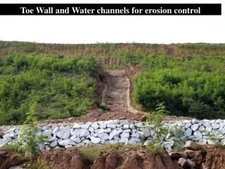
Bank-Toe Protection • Re-open BSTEM-5.0.xls • Select “Input Geometry sheet” • Select Option B • Input these values: • Input channel and flow parameters • Click “Run Bank Geometry Macro” • Open “Bank Material” sheet • Select “Moderate silt” for all layers • Select “Toe Model Output” sheet • Click “Run Toe-Erosion Model”