Download
1 / 46
500 likes | 998 Views
Gas turbine cycles for aircraft propulsion. In shaft power cycles, power is in form of generated power. In air craft cycles, whole power is in the form of thrust. Propulsion units include turbojets, turbofans and turboprops

E N D
Gas turbine cycles for aircraft propulsion • In shaft power cycles, power is in form of generated power. In air craft cycles, whole power is in the form of thrust. • Propulsion units include turbojets, turbofans and turboprops • In turbojets and turbofans, the whole thrust is generated in propelling nozzles. In turboprops, most of the thrust is produced by a propeller with only a small contribution from exhaust nozzle.
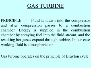
Gas turbine cycles for aircraft propulsion • Turbojet The turbine is designed to produce just enough power to drive the compressor. The gas leaving the turbine at high pressure and temperature is expanded to atmospheric pressure in a propelling nozzle to produce high velocity jet. The propelling nozzle refers to the component in which the working fluid is expanded to give a high velocity jet.
Gas turbine cycles for aircraft propulsion • Turbojet
Gas turbine cycles for aircraft propulsion • Turbojet
Turbofan • Turbofan Part of the air delivered by an LP compressor or fan bypasses the core of the engine (HP compressor, combustion and turbines) to form an annular propulsive jet or cooler air surrounding the hot jet. This results in a jet of lower mean velocity resulting in better propulsive efficiency and reduced noise.
Turboprop • Turboprop For lower speed, a combination of propeller and exhaust jet provides the best propulsive efficiency. It has two stage compressor and ‘can-type’ combustion chamber. Turboprops are also designed with a free turbine driving the propeller or propeller plus LP compressor (called free-turbine turboprop).
Performance Criteria • The net momentum thrust is due to the rate of change of momentum • Ca is the velocity of air at inlet relative to engine • Cj Velocity of air at exit relative to engine. • The net pressure thrust is • Thus, the total thrust is
The propulsion efficiency • Propulsive efficiency is a measure of the effectiveness with which the propulsive dust is being used for propelling the aircraft but it is not the efficiency of energy conversion.
The propulsion efficiency • Energy conversion efficiency • Overall efficiency
The propulsion efficiency • Specific fuel combustion: fuel consumption per unit thrust, i.e. kg/h N = 0.12 • Specific thrust, Fs
Thermodynamics of air craft engines • Diffuser: Velocity decreases in diffuser while pressure increases • Nozzle: Velocity increases in nozzle while pressure decreases
Thermodynamics of air craft engines • Isentropic efficiency of a diffuser
Thermodynamics of air craft engines The rest of the components ( compressor, turbine combustion chamber) are treated before. The ram efficiency is Propelling nozzle Propelling nozzle is the component in which the working fluid is expanded to give a high velocity jet. Nozzle Efficiency for adiabatic flow
Thermodynamics of air craft engines for unchoked nozzle (Mj<1); P5=Pa For choked nozzle ( Max. rate is reached) M=1, P5=Pc To check if it is choked or not
Thermodynamics of air craft engines for choked condition M=1 But isentropic efficiency is
Thermodynamics of air craft engines Pc is calculated as substituting for
Thermodynamics of air craft engines To calculate A5 of nozzle
Thermodynamics of air craft engines Example Simple turbojet cycle
Thermodynamics of air craft engines Example:2: Turbofan Analysis Overall pressure ratio given sea level Pa=1 bar Ta=288 K
Thermodynamics of air craft engines State 1 is sea level since Ca=0.0 Required: sfc, Fs
Thermodynamics of air craft engines check for choking of both nozzles ( hot and cold)
Thermodynamics of air craft engines C7= 476 m/s for cold nozzle ( do same) note: Nozzles are independent of each other regarding choking.
Thermodynamics of air craft engines Notes: a8=344.2; M8<1