UMaine Aero Design
240 likes | 631 Views
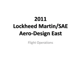
UMaine Aero Design. Proposed Spring Timeline. Major Tasks. Fuselage Engine/Wing/Payload Mounts The Wing Mockup RC & Servo Control Tail Assembly. Full Scale Balsa Wing Mockup.

UMaine Aero Design
E N D
Presentation Transcript
Major Tasks • Fuselage • Engine/Wing/Payload Mounts • The Wing • Mockup • RC & Servo Control • Tail Assembly
Full Scale Balsa Wing Mockup • After the wing design and sizing was completed at the end of semester 1, it was decided to build a 1:1 model of the right pinion of the wing. This was to incorporate all design features set forth previously • Reasons for Creating the Mockup: • Gain Construction Experience • Validate Methods and Techniques as Reasonable and Provide A Basis for Improvements in Efficiency • Generate a Platform for Testing of Control System Implementation • Create a Structural Model For Physical Testing • Estimate the Weight of the Aircraft By Extrapolation of Pinion Weight
Full Scale Balsa Wing Mockup (cont.) • Setup and Building Process • Ribs cut by hand with spar indentations and lightening holes in place • Half-wing planform drawn out in full scale on plywood base • Base elevated at one end to provide designed dihedral • Additional measured pads of increasing thickness placed under trailing edges to obtain wing twist. • Balsa supports glued to base (two per rib) to hold components vertical during construction • Leading edge set in place with epoxy • Balsa spars set with CA • Spar rectangular beam walls added • Sheeting added on trailing and leading edges, as well as over first seven ribs for additional rigidity in bending
Full Scale Balsa Wing Mockup (cont.) • Items Learned By Completing the Mockup: • Dihedral built into wing is an unnecessary complication • Method for raising the trailing edge must be altered • Cutting pieces by hand is time consuming – utilize a more precise industrial method • Make ribs thinner • Use a manufactured leading edge in place of dowel and cutout • Place additional support and reinforcement at taper/constant chord joint • Solid wing relatively impractical • Sheeting over all curvatures is not feasible without altering ribs or adding material in sections
Structural Manufacturing • Epilog Laser Engraving Systems • 60 Watt Dual Helix CO2 Laser • Capable of cutting and engraving several different types of materials, as shown in the table to the left
Structural Manufacturing • Efficiently, accurately, and quickly cuts and engraves any image imported from CorelDRAW software • Our two airfoil designs were cut in 1:25
Fuselage Design and Construction • The original fuselage idea was to have a large, short in length main compartment that held all of the components with twin booms coming off of the wings. Much like the Cessna O-2 Skymaster seen below. • However…
The group foresaw fabrication difficulties with affixing the twin booms to the wings with the current design of the wing. Modifications would have to be done on the current wing design to incorporate a twin boom fuselage-empennage design.
Option 2: Single Boom • The fuselage is shaped much like that of a commercial aircraft, long and narrow but instead of the entire fuselage-empennage being enclosed, a single boom will extend from the back of the fuselage to the empennage.
Design Consideration • Fabrication • Will construction be reasonable? • Spacing • Is there enough room for all of the components? • Functionality • Is everything easily accessible? • Can the Payload be removed and re-placed in the one minute time limit as required by rules?
Spacing • A very rough solid works model was drawn up with all necessary components to be housed in the fuselage. The main goal was to have enough space for everything to fit and be easily accessible. Thus aerodynamics is not a large concern in comparison to the spacing.
Fabrication Considerations • The fuselage in it’s final design is to be constructed of a ribs that make up the shape of the fuselage, with spars acting as it’s support as shown below. These ribs are also easily cut out using the laser at the Advanced Structures and Composites Center.
Going Forward • The method in which the top-mounted wing will be affixed to the fuselage still needs to be decided upon in order to finalize the design. • The material in consideration for the boom right now is PVC, however calculations need to be performed to know it can withstand certain loads without too much deflection. • Weight reduction: • Total Weight for fuselage frame and boom = .97lbs (according to SolidWorks) • There is room for reduction if the boom is shortened.
Control Surface • Transmitter: • 10 model memory • Servo Monitors • Trainer Mode • Trim Adjustment • Throttle Cut • Receiver: • 6 Channels • Battery Operated • Rechargeable
Servo and Servo Linkage 6 Channels - Throttle - Flaps - Roll, Pitch, and Yaw
Control Surfaces The control surfaces cause a moment about the center of gravity of the vessel, allowing the plane to maneuver in whatever fashion the controller wishes. Ailerons: Located on each wing cause the vessel to roll as one aileron goes down producing more life on that side of the aircraft and the opposite side goes up producing less lift. Elevator: Located on the Tail Assembly, when angled the resulting lift either raises the rear of the aircraft (pointing the nose down) or lowers it (pointing the nose skyward). Rudder: Enables the plane to turn left or right on the “yaw” axis. Flaps: Located on the wing, close to the fuselage, their purpose is to increase lift which allows to land or takeoff at slower speeds
Recent Developments in Tail Assembly Design • Twin-boom design abandoned in favor of • the standard single-boom design • Approximate sizing of horizontal and vertical stabilizers • completed based on generally accepted rules • for tail assembly sizing (from MIT OCW course • notes on aircraft design) Part of the Tail Assembly Sizing Mathcad Sheet
The Future of Tail Assembly Design • Airfoil selection for horizontal • and vertical stabilizers • Obtain a solution (iteratively) for • size, location, and incidence angles • of stabilizers. • Solid Modeling of tail assembly, boom, and connection to fuselage
New Goals • SolidWorks of the wing and fuselage ribs • Laser cut • Servos and control • Ailerons on mock-up • Tail-Assembly • Structural Analysis • Materials selection • Laser cut