Download

1 / 36
390 likes | 998 Views
Chapter 10 The Traditional Approach to Design. Systems Analysis and Design in a Changing World, 5th Edition. Learning Objectives. Describe the steps involved in the traditional approach to designing the application architecture Develop a system flowchart

E N D
Chapter 10 The Traditional Approach to Design Systems Analysis and Design in a Changing World, 5th Edition
Learning Objectives • Describe the steps involved in the traditional approach to designing the application architecture • Develop a system flowchart • Develop a structure chart using transaction analysis and transform analysis • Write pseudocode for structured modules • Explain how to use three-layer design with the traditional approach
Overview • Traditional approach to designing software • Overview of structured models, model development process, related terminology • How data flow diagrams are annotated with automation boundary information • How analysis phase models are transformed into design models using system flowcharts, structure charts, and module pseudocode • Integration into other design phase activities • Applying approach to a three-layer architecture
The Structured Approach to Designing the Application Architecture • Application software programs • Designed in conjunction with database and user interface • Hierarchy of modules • Design internal logic of individual modules • Top-down approach • DFDs with automation boundaries • System flowcharts, structure charts, pseudocode
Structured Design Models Figure 10-1
The Automation System Boundary • Partitions data flow diagram processes into manual processes and automated systems • Processes can be inside or outside boundary • Data flows can be inside and outside of boundary • Data flows that cross system boundary represent inputs and outputs of system • Data flows that cross boundaries between programs represent program-to-program communication
DFD with Automation System Boundary Figure 10-2
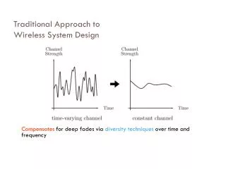
The System Flowchart • Representation of various computer programs, files, databases, and associated manual processes that make up complete system • Frequently constructed during analysis activities • Graphically describes organization of subsystems into automated and manual components • Can show type of transaction processing system • Batch • Real-time
Common System Flowchart Symbols Figure 10-3
Sample System Flowchart for Payroll System Figure 10-4
System Flowchart for RMO Figure 10-5
The Structure Chart • Describes functions and subfunctions of each part of system • Shows relationships between modules of a computer program • Simple and direct organization • Each module performs a specific function • Each layer in a program performs specific activities • Chart is tree-like with root module and branches
A Simple Structure Chart for the Calculate Pay Amounts Module Figure 10-6
Structure Chart Symbols Figure 10-7
Structure Chart for Entire Payroll Program Figure 10-8
Developing a Structure Chart • Transaction analysis • Uses system flow chart and event table inputs • Upper-level modules developed first • Identifies each transaction supported by program • Transform analysis • Uses DFD fragments for inputs • Computer program “transforms” inputs into outputs • Charts have input, calculate, and output subtrees
Event-partitioned DFD for the Order-Entry Subsystem Figure 10-9
High-Level Structure Chart for the Order-Entry Subsystem After Transaction Analysis Figure 10-10
Steps to Create a Structure Chart from a DFD Fragment • Determine primary information flow • Main stream of data transformed from some input form to output form • Find process that represents most fundamental change from input to output • Redraw DFD with inputs to left and outputs to right – central transform process goes in middle • Generate first draft of structure chart based on redrawn data flow
The Create New Order DFD Fragment Figure 10-11
Decomposed DFD for Create New Order Figure 10-12
Rearranged Create New Order DFD Figure 10-13
First Draft of the Structure Chart for Create New Order Figure 10-14
Steps to Create a Structure Chart from a DFD Fragment • Add other modules • Get input data via user-interface screens • Read from and write to data storage • Write output data or reports • Add logic from structured English or decision tables • Make final refinements to structure chart based on quality control concepts
The Structure Chart for the Create New Order Program Figure 10-15
Combination of Structure Charts: Transaction and Transform Analysis Figure 10-16
Evaluating the Quality of a Structure Chart • Module coupling • Measure of how module is connected to other modules in program • Goal is to be loosely coupled • Module cohesion • Measure of internal strength of module • Module performs one defined task • Goal is to be highly cohesive
Examples of Module Cohesion Figure 10-17
Module Algorithm Design—Pseudocode • Describes internal logic of software modules • Variation of structured English that is closer to programming code • Syntax should mirror development language • Three types of control statements used in structured programming • Sequence – sequence of executable statements • Decision – if-then-else logic • Iteration – do-until or do-while
Pseudocode for Calculate Pay Amounts Figure 10-18
Integrating Structured Application Design with Other Design Tasks • Structure chart must be modified or enhanced to integrate design of user interface and database • Are additional modules needed? • Does pseudocode in modules need modification? • Are additional data couples needed to pass data? • Structure charts and system flowcharts must correspond to planned network architecture • Required protocols, capacity, and security
Three-Layer Design • Three-layer architecture • View layer, business logic layer, and data layer • Structure charts and system flowcharts describe design decisions and software structuring • Employs multiple programs for user interface, business logic, and data access modules • Modules in different layers communicate over real-time links using well-defined protocols
System Flowchart Showing Three-Layer Architecture for Customer Order Figure 10-19
Structure Chart Showing Three-Layer Architecture for Create New Order Figure 10-20
Summary • For traditional structured approach to systems design, primary input is data flow diagram • DFD is enhanced by adding system boundary • Designer describes processes within each DFD boundary using one or more structure charts • Structure charts developed using • Transaction analysis – multiple transaction types • Transform analysis – single transaction from input to output
Summary (cont’d) • Structure charts may be based on three-layer architecture • Modules will be clearly identified by layer • Structure chart may be decomposed if layers execute on multiple systems • Structured design may also include • System flowcharts to show data movement • Module pseudocode to describe internal logic of structure chart module