Download
1 / 49
570 likes | 991 Views
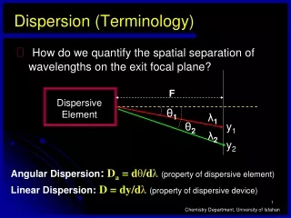
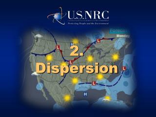
2. Dispersion. Meteorological Fundamentals. Diffusion, Transport, Dispersion. Diffusion answers “How much of the pollutant reaches a location?” Transport answers “Where does the pollutant travel to following release?” “What was the footprint on the ground?”

E N D
Meteorological Fundamentals 2009 National Radiological Emergency Planning Conference
Diffusion, Transport, Dispersion • Diffusion answers “How much of the pollutant reaches a location?” • Transport answers “Where does the pollutant travel to following release?” “What was the footprint on the ground?” • As the terrain gets more complex, transport takes on more significance. A large source of uncertainty. • Dispersion is the result of diffusion and transport. 2009 National Radiological Emergency Planning Conference
Snapshot, Spatial, and Temporal • Snapshot refers to a projection based on a initial set of conditions, persisted without change. • e.g., “straight line” Gaussian. • Spatial refers to the ability to represent impacts on the plume after release from site. • e.g., plume bending to follow river valley, sea breeze circulation. • Temporal refers to the ability of model to reflect input data changes over time. • e.g., change in release rate; meteorology. 2009 National Radiological Emergency Planning Conference
Earth’s Heat Balance (typical) 2009 National Radiological Emergency Planning Conference
Earth’s Heat Balance (typical) 2009 National Radiological Emergency Planning Conference
Energy Distribution • Since the heat balance varies as a function of: • Time of day • Cloud cover • Surface cover • Vegetation / Desert / Bodies of water • Urban heat islands --there is an unequal distribution of energy across the earth, causing differences in temperature and pressure. • Weather as we know it is largely the result of these differences in energy distribution. 2009 National Radiological Emergency Planning Conference
Horizontal Winds • Horizontal winds are created by differences in local pressures, both local and global. • Wind flows from higher pressure air masses to lower pressure air masses. • Since the distribution of air masses varies, so do winds. • Lower surface winds typical at night. • Because of surface friction, wind speeds generally increase with height. • Gradient depends on surface texture and turbulence in atmosphere. 2009 National Radiological Emergency Planning Conference
Wind Speed Gradients 2009 National Radiological Emergency Planning Conference
Atmospheric Stability • The temperature of the lowest layer of the atmosphere (troposphere) generally increases with decreasing height • This gradient is known as the atmospheric lapse rate: • On average, the atmospheric lapse rate is about +6.5ºC per kilometer of elevation • Typically referred to as delta-T in nuclear power community • By convention, lapse rate is always the higher elevation temperature less the lower elevation temperature 2009 National Radiological Emergency Planning Conference
Atmospheric Stability • Overall lapse rate through the troposphere is positive • ( i.e., “positive” with decreasing height) • In the lower kilometer, lapse rate varies with the daily cycle of heating and cooling • This daily variation has significant impact on diffusion • Thermal gradients are created, resulting in thermal currents and turbulence • Atmospheric stability is an index of the amount of atmospheric turbulence present • The greater the turbulence, the better the diffusion 2009 National Radiological Emergency Planning Conference
Atmospheric Stability • Unstable Atmosphere • Positive lapse rate (increases with decreasing height) • Warmer buoyant air near surface rises • Strong convective air currents favor diffusion • Neutral Atmosphere • No change of temperature with height • Stable Atmosphere • Negative lapse rate (decreases with decreasing height) • Little or no vertical currents disfavor diffusion • Mostly at night; also known as inversion 2009 National Radiological Emergency Planning Conference
Impact of Stability on Diffusion • Consider parcel of air injected into the atmosphere by a motive or buoyant force: • Parcel does not mix with surrounding air • Parcel will expand or contract as the pressure of air surrounding the parcel changes • If parcel is less dense than the surrounding air, the parcel will rise • As the parcel expands or contracts, its temperature and density will change 2009 National Radiological Emergency Planning Conference
Impact of Stability on Diffusion • The parcel temperature decreases at a constant rate of 10ºC per kilometer • Known as the dry adiabatic lapse rate • The atmosphere temperature is also changing as a function of the measured atmospheric lapse rate • As such, the parcel movement is a function of the measured atmospheric lapse rate • The more positive the measured atmospheric lapse rate is, the greater the parcel rise, the better the diffusion 2009 National Radiological Emergency Planning Conference
Impact of Stability on Diffusion • Shown here is a situation involving an unstable atmosphere • Atmospheric lapse rate is positive, temperature and pressure increases with decreasing height • Parcel of air rises as long as its density is less than that of the surrounding atmosphere 2009 National Radiological Emergency Planning Conference
Impact of Stability on Diffusion • Within the troposphere, it is possible to have multiple layers, each with its own atmospheric lapse rate • Figure shows a neutral stability layer topped by a stable layer (e.g., Sunrise as earth heating burns away inversion layer) • The stable layer aloft “caps” the vertical rise • The release mixes in the neutral layer • The height of the lower layer is known as the mixing depth 2009 National Radiological Emergency Planning Conference
Diffusion Models 2009 National Radiological Emergency Planning Conference
Basic Concept • Release of a material to environment • Certain volume • Certain radionuclide concentration • Release mixes with air due to turbulence • Release increases in volume • Release decreases in concentration • Resulting concentration is not uniform • Most mixing occurs at the surface of the release volume • Concentration greatest at center of release volume, decreases asymptotically 2009 National Radiological Emergency Planning Conference
Atmospheric Dispersion Models • Gaussian plume model most widely used for estimating dispersion in dose projections • Generally non-spatial and non-temporal • Stylized, straight-line “snapshot” • Simple, can be implemented in hand calculations • May not be representative for a given site • Advanced models are available • Segmented-plume Gaussian models • Modified potential flow numerical models • Particle tracking models 2009 National Radiological Emergency Planning Conference
Gaussian Model Plume concentration is assumed to diffuse in the vertical by a normal distribution, represent-ed by the standard deviation, y There is also diffusion downwind (x) but this is small compared to the distribution by the wind, represented by the wind speed, U Plume concentration is assumed to diffuse in the horizontal (cross-wind)by a normal distribution, represented by the standard deviation, z 0,0,0 2009 National Radiological Emergency Planning Conference
Effective Plume Height • For elevated plumes, the plume will raise above the stack height due to thermal buoyancy and other forces • Increases in terrain height change the position of the receptor relevant to the plume and, if high enough, can obstruct the plume 2009 National Radiological Emergency Planning Conference
Gaussian Model • Essential conditions: • Non-zero wind speed • Wind direction constant over time and downwind area • Release rate constant over time for the duration of the release • Atmospheric stability constant over time and downwind area • Because of these conditions: • Gaussian assessment is a straight-line, “snapshot” • Gaussian model is not temporal nor spatial 2009 National Radiological Emergency Planning Conference
Gaussian Model Xxyz = Downwind concentration at coordinates X,Y,Z (e.g., Ci/M3) Q’ = Release rate (e.g., CI/sec) x = Receptor downwind distance (along wind) y = Receptor horizontal (crosswind) offset from plume centerline z = Receptor height (ground level =0) he = Plume centerline effective height above terrain u = Wind speed y,z = Dispersion Coefficient on Y-axis and Z-axis 2009 National Radiological Emergency Planning Conference
Dispersion Coefficients • Input parameters can be measured or projected • y and z vary as functions of the downwind distance and atmospheric stability class • Values were determined by correlations to experimental field measurements. • Correlations by Pasquill and Gifford typically used • There are other datasets 2009 National Radiological Emergency Planning Conference
P-G Dispersion Coefficients σ y z 2009 National Radiological Emergency Planning Conference
Gaussian Model If the receptor is at ground level, z = 0, and: If the receptor is at ground level under plume centerline, z = 0, y=0, and: If the receptor and plume is at ground level, he= 0, and: 2009 National Radiological Emergency Planning Conference
Normalized Air Concentration • The preceding equations are often restructured to calculate normalized airborne concentration, or /Q • Normalized concentration = divided by Q • where = airborne radionuclide concentration, e.g., Ci/m3 • Q = source term, Ci/s and • /Q = s/m3 2009 National Radiological Emergency Planning Conference
Gaussian Model Enhancements • Most limiting aspect of basic Gaussian model is inability to evaluate spatial and temporal differences in model inputs • Enhanced Gaussian models can address these inabilities • Puff model • Segmented plume models • Enhanced Gaussian models generally address both diffusion and transport 2009 National Radiological Emergency Planning Conference
Enhanced Gaussian Model Structure • Processing algorithm that: • Divides the calculation domain into equal time steps • Assign meteorological and release data to each time step • Processes each time step individually, integrating the calculation results • Use of time steps allow model to reflect temporal changes • A rectangular two-dimensional (x,y) wind field • Each cell is assigned a wind vector for each time step • The wind vector assigns the initial conditions for that time step 2009 National Radiological Emergency Planning Conference
Gaussian Model Enhancements • Segmented Plume • Plume is approximated by a series of straight-line Gaussian plumes, each estimated on the parameter values applicable to that time step • Puff Model • Plume is approximated by a series of puffs, the diffusion and transport of each is estimated on the parameter values applicable to that time step 2009 National Radiological Emergency Planning Conference
Segmented Plume Model Screen capture from MIDAStm software by PLG, Inc. 2009 National Radiological Emergency Planning Conference
Advanced Diffusion Models 2009 National Radiological Emergency Planning Conference
Advanced Models • In many Gaussian models, terrain height is addressed only in determining the effective plume height • The impact of terrain on plume transport is not addressed • Straight-line models can not “curve” a plume around mountains or follow a river valley • Advanced models can address terrain impact on plume transport 2009 National Radiological Emergency Planning Conference
Advanced Models • In a particle-in-cell (PIC) model, the wind field is three-dimensional • Wind vectors have x,y,z components • Calculated for each time step using modified potential flow algorithms • Requires wind speed and direction data for multiple elevations • Terrain displaces affected wind field cells; wind vectors for these cells = 0 2009 National Radiological Emergency Planning Conference
Dispersion in Advanced Models • In lieu of Gaussian formulation, PIC models use large numbers of virtual particles, each of which are tagged with: • Time step of injection into wind field • Radionuclide characterization • Three-axis diffusion coefficient • A group of particles is created for each time step, and injected into the wind field in sequence 2009 National Radiological Emergency Planning Conference
Dispersion in Advanced Models • The particles disperse through the wind field • Movement depends on three-axis diffusion coefficients and three-axis wind field vectors • On encountering a terrain face, particles follow vectors into adjacent cells, moving around or over the terrain • Particle positions are periodically recorded and integrated over time • When dispersion is complete, the integrated particles in each cell are converted to concentrations and then dose • Inhalation dose assigned only for particles in cell layer adjacent to the ground • Ground deposition can only occur from the cell layer adjacent to the ground 2009 National Radiological Emergency Planning Conference
Particle Tracking Model During projection, the wind shifted around from down-river (left), CCW to upriver Screen capture from MIDAStm software by PLG, Inc. 2009 National Radiological Emergency Planning Conference
Particle Tracking Model Screen capture from MIDAStm software by PLG, Inc. 2009 National Radiological Emergency Planning Conference
Inputs to Dispersion Models • Wind speed • Wind direction • Ambient temperature • Release height • Rainfall • Stability class 2009 National Radiological Emergency Planning Conference
Inputs to Dispersion Models • A straight-line Gaussian model can generally be driven by a single set of meteorological data • Non-temporal; non spatial • Wind field models can often be driven by multiple meteorological stations • Temporal and spatial • Improves modeling in complex terrain • A wind field model driven by a single meteorological tower may not provide results any better than those from a straight-line Gaussian model • Highly dependent on surrounding terrain and meteorological regimes • Additional meteorological towers may be necessary to adequately model sea breeze sites 2009 National Radiological Emergency Planning Conference
Elevated vs Ground Level Plumes Ground LevelConcentration Ground LevelConcentration 2009 National Radiological Emergency Planning Conference
Terrain and Building Impacts on Diffusion Models 2009 National Radiological Emergency Planning Conference
Transport and Diffusion at Coastal Sites • Sea Breeze • Also applies to any other large body of water • Caused by differences in temperature of the air above water versus that above land after sunrise • If the regional wind flow is light, a circulation will be established between the two air masses • At night, the land cools faster, and a reverse circulation (weak) may occur 2009 National Radiological Emergency Planning Conference
Impact of Sea Breeze • The air over the water is cooler and is stable • As the sea breeze forms, the stable air flows over the unstable air mass at the shore • The boundary between the stable and unstable air is known as the thermal internal boundary layer (TIBL) • Because the air below the TIBL is unstable, there is turbulence and mixing, drawing the plume to ground level • As the day progresses, the TIBL layer moves inland 2009 National Radiological Emergency Planning Conference
Impact of Sea Breeze 2009 National Radiological Emergency Planning Conference
Transport and Diffusion at Valley Sites 2009 National Radiological Emergency Planning Conference
Transport and Diffusion at Valley Sites 150 ft 500 ft 35 ft 2009 National Radiological Emergency Planning Conference
Building Wake A sharp edged building would create more streamline distortion and turbulence than shown here 2009 National Radiological Emergency Planning Conference
Building Wake If the stack (plus plume rise) isn’t high enough, the plume could be drawn into the building wake. Although mixing would occur, the plume would be at ground level sooner than projected 2009 National Radiological Emergency Planning Conference