Download
1 / 6
60 likes | 189 Views
This document presents an analysis of power consumption in the RT CH section, focusing on the voltage definitions for synchronous particles in cavities. The study includes figures illustrating field distribution and beam energy gain in cavity setups. A comparison of cavity voltage definitions across different types of cavities is provided. Notably, the findings indicate that power consumption remains consistent for various designs despite differing cavity types. This research is essential for optimizing performance in accelerator technologies.

E N D
Power consumption in RT CH sectionV. Aseev (FNAL) P. Ostroumov (ANL)G. Romanov(FNAL)November 29, 2007
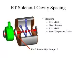
MWS cavity voltage definition. The cavity voltage defined for synchronous particle Fig1. The Field distribution in RT cavity #2. A beam energy gain in cavity and another cavity voltage definition Fig.2 The cavity #2 voltage. Comment: Piter defined cavity voltage as
Table 1: The cavity parameters in the RT section, 9 cavity types.
Conclusion. Power consumption in RT CH section for 16 cavity and 9 cavity types design is practically the same.