Download
1 / 34
360 likes | 842 Views
Introduction to Repeaters. Ron Milione, Ph.D. CETma W2TAP w2tap@arrl.org ron.p.milione.ctr@us.army.mil. What is a repeater?. A repeater is a device that performs 3 basic functions: It receives and demodulates an RF signal. It regenerates the audio information.

E N D
Introduction to Repeaters Ron Milione, Ph.D. CETma W2TAP w2tap@arrl.org ron.p.milione.ctr@us.army.mil
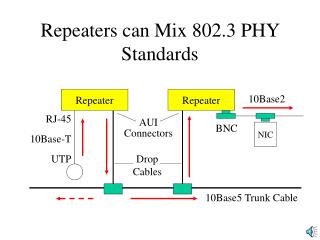
What is a repeater? • A repeater is a device that performs 3 basic functions: • It receives and demodulates an RF signal. • It regenerates the audio information. • It modulates and retransmits the audio on a new RF carrier.
Some History… • Amateurs experimenting with VHF/UHF in the 1930’s discovered that propagation was generally limited to line-of-sight. • The limited working range offset the advantages of VHF gear for mobile/portable operation (small antennas and light equipment) • In the 1950’s, widespread availability of WWII surplus electronics led to the creation of the first repeaters on the West Coast. • The repeaters were AM and used frequencies on the 2 meter band. • By the 1970’s, standard offsets and FM were introduced.
Antenna • Repeater antennas are almost always vertically polarized and have an omnidirectional azimuth pattern. • Generally the same antenna is used for transmitting and receiving. • The antenna is mounted as high as possible in order to have good line-of-sight coverage.
Duplexer • A duplexer is a special type of filter that allows a single antenna to transmit and receive simultaneously on two closely spaced frequencies. • A typical duplexer consists of two pairs of resonant cavities. • Two pass the transmit signal from the transmitter to the antenna while rejecting the received power. • The other two pass the receive signal from the antenna to the receiver while rejecting transmitted power. • Typical rejection is better than 70 dB, while attenuating the desired signal less than 2 dB
Receiver • A repeater receiver must have good sensitivity and excellent selectivity, in order to have adequate rejection of the transmitted signal. • The receiver will have at least two outputs: • Audio output • Carrier detect • The audio output can contain both audio signals and out-of-band control tones. • A signal appears on the carrier detect line when an RF carrier breaks the receiver’s squelch. (a repeater use requests service)
Carrier Operated Relay • The carrier operated relay turns on the transmitter in response to: • a carrier detect signal • an ID transmit signal
Transmitter • The transmitter should meet the following criteria: • High spectral purity (to avoid unnecessary receiver interference) • Highest possible output power (for greatest coverage)
ID Timer • The ID timer performs basic ID housekeeping tasks: • Generating appropriate ID’s • Tracking time between ID transmissions
External Control • The control operator (repeater trustee or his designee) needs to be able to control the operation of the repeater transmitter, in the event of: • Electrical malfunction • Inappropriate use of the repeater • To implement the external control function as well as some other desirable features, the carrier operated relay is generally replaced by a repeater controller
Repeater Controller • A repeater controller provides (at least) the following capabilities • Telephone line interface • Voice ID and announcement capability • Linking • Transmitter controls • Special supervisory tones (courtesy beep, etc.) • DTMF decoding • CTCSS decoding
Types of External Control • Via telephone • The repeater operation is controlled through DTMF tone groups sent through a phone line. • Via RF link • The repeater controller is accessed via a separate simplex RF link (above 222.15 MHz) • On-the-Air • DTMF tones sent into the repeater are used to control its operation.
Autopatch • An autopatch is a connection between an amateur repeater and the PSTN that permits a repeater user to make a phone call from his/her radio, provided that the radio has DTMF capability. • The call made through the autopatch is subject to all the restrictions of an amateur transmission. • The popularity and utility of of autopatch has declined significantly with the advent of cell phones.
Reverse Autopatch • A reverse autopatch is a connection from the PSTN to an amateur station through a repeater. • The call is originated by the PSTN subscriber, not the mobile amateur. • The originator of the call should be an amateur – the call will be carried on amateur frequencies • Once again, the restrictions on amateur transmissions apply to these communications.
Implementing Autopatch • All modern repeater controllers have an autopatch capability. All that is required is a connection between the phone line and the controller. • Cell phones may also be used to provide a line for autopatch. If the line will also be used to control the repeater, an older AMPS cell phone is necessary.
CTCSS • CTCSS is the “continuous tone coded squelch system” • A repeater using CTCSS will cannot be accessed unless a user transmits a subaudible tone with his audio information.
Repeater Linking • Repeaters may be linked to increase the coverage available to the users. • Linking methods: • Internet – ilink, etc. • Telephone line • VHF/UHF link between repeaters (remote base linking)
Internet Repeater Linking • This type of linking uses VoIP (Voice over Internet Protocol) to connect repeaters via the Internet. • The repeater is connected to the Internet via a PC running software such as Ilink, Echolink, IRLP/Speak Freely • The software provides A/D conversion and compression for the audio and transceiver control. • The repeater may be accessed from the Internet by users who have VoIP capability
Telephone Linking • Uses a dial-up link to connect two repeaters. • Primary repeater’s controller makes an autopatch call to the secondary repeater. • The secondary repeater’s controller answers the call and goes into reverse autopatch mode. • This type of linking is full duplex
Remote Base Linking • A separate RF link is installed between the primary and secondary repeaters. • FCC rules require that this link operate above 222.15 MHz • When the primary repeater is opened, its controller routes audio to the RF link transceiver and puts it into transmit mode. • When the secondary repeater’s RF link transceiver receives a signal, this signal is sent to its controller, which retransmits the signal over the secondary repeater. • This type of linking is half-duplex (simplex)
Some Notes on Repeater Operation • All transmission over a repeater should be in accordance with FCC Rules. • Amateurs have no “right” to operate on a repeater. The repeater or his/her designee grants operating privileges to amateurs. • Wait for the courtesy tone!!!! • The repeater should not be tied up by long conversations – use a simplex frequency for a long QSO.
Closing Comments • FM Repeater operation is often the first type a new amateur attempts, and is the main mode for many amateurs • All repeater users should be polite, courteous and helpful to newcomers/visitors • The W2VL repeater is flagship repeater of LIMARC • 146.850- W2VL 1288.00- • 147.375+ W2KPQ 224.820- • 449.125- W2KPQ • PL for all is 136.5