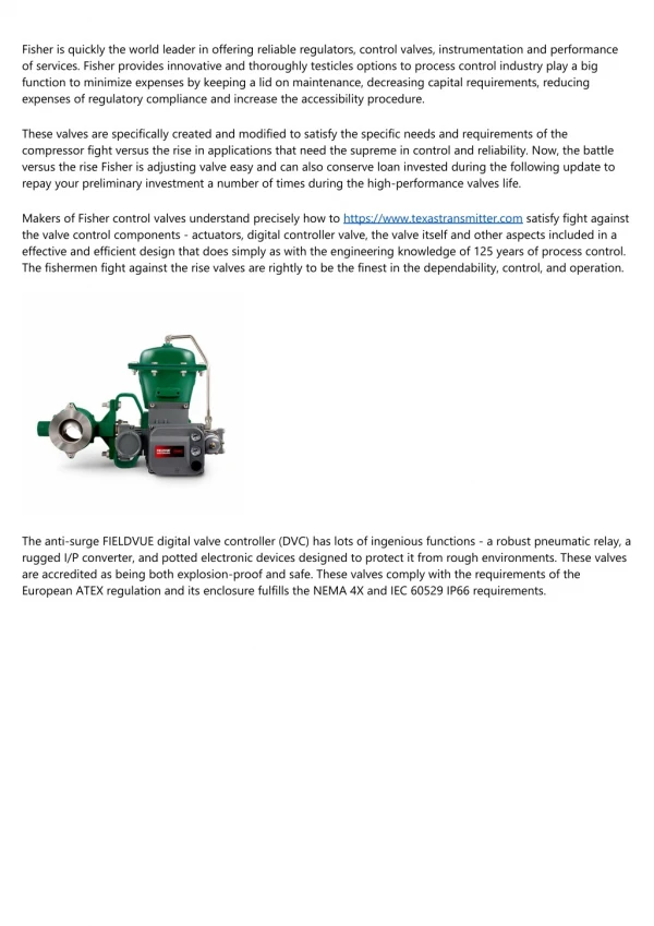
Download
1 / 28
480 likes | 2.24k Views
Pneumatics – Module 3. Directional control valves. Objectives. Differentiate between the main types of directional control valves. Explain the function of each type of directional control valves. Demonstrate the function and uses of 3/2 way valve, (N/C) push button actuated.

E N D
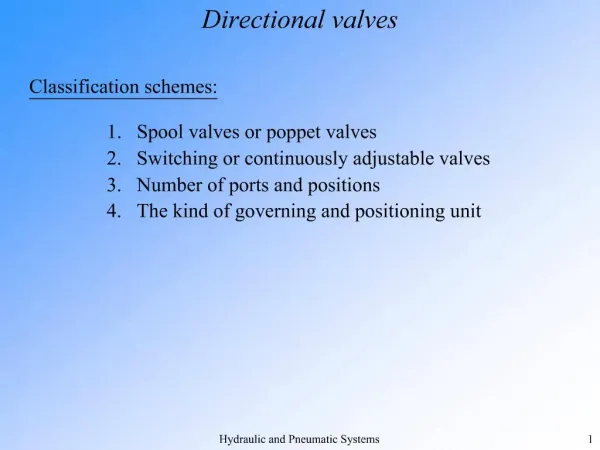
Pneumatics – Module 3 Directional control valves
Objectives • Differentiate between the main types of directional control valves. • Explain the function of each type of directional control valves. • Demonstrate the function and uses of 3/2 way valve, (N/C) push button actuated. • Demonstrate the function and uses of 3/2 way valve, (N/O) push button actuated. • Demonstrate the function and uses of 3/2 way valve, (N/C) roller lever actuated. • Explain the function and uses of 5/2 way valve, selector valve. • Explain the function and uses of 5/2 way valve, single pilot valve. • Explain the function and uses of 5/2 way valve, double pilot valve. • Use the FluidSIM software to build and simulate a pneumatic circuits that contain DCV • Build a pneumatic circuit using DCV on the Festo trainer and check its operation • Design simple pneumatic circuits for a given application.
Introduction • Directional control valves are devices which influence the path taken by an air stream. • The directional control valve is represented by two numbers. The first number represents the number of ports, and the second number represents the number of positions. • Note: These symbols do not provide any information about the constructional design, but just indicate the function of the valve.
Directional Control Valves (DCV) 5/2 WAY 3/2 WAY 3/2 way DCV (N/C) 5/2 way DCV 5/2 way Selector Valve 3/2 way DCV (N/O) 3/2 way Roller Valve 5/2 way Single Pilot 3/2 way Selector Valve 5/2 way Double Pilot
3/2 way DCV (Directional Control Valve) – NC (Normally closed) • A 3/2-way valve has 3 ports (1, 2 and 3) and 2 switching positions (before operating and after operating). • It is represented by the normal position. • Normally closed means that compressed air cannot flow through the valve
3/2 way DCV (Directional Control Valve) – NC (Normally closed) Un-Actuated In normally closed 3/2 way valve, a spring-loaded disk seal blocks the air flow from the air supply port (1) to the working port (2). The working port (2) is connected with exhaust port (3). Actuated Actuating this valve results in allowing the flow from port (1) to port (2) and blocking the exhaust port (3).
3/2 way DCV (Directional Control Valve) – NO (Normally Open) • Normally open means that compressed air flows through the valve. • When the pushbutton is actuated the valve is closed, thus stopping the air to flow from port (1) to port (2).
3/2 way DCV (Directional Control Valve) – NC (Normally closed) Un - actuated • In the normally open 3/2 way valve, a spring loaded disk blocks exhaust port (3). The air supply port (1) is connected to the working port (2). Actuated Actuating this valve results in allowing the flow from port (2) to port (3) and blocking the supply air port (1). Fig. (3.5.b) shows the ISO symbol of 3/2 way valve normally open (N/O) and spring reset,
3/2 way Roller Lever Valve (N/C) • The roller lever actuation way is considered to be one of the most important types of valve actuation that is used for automatic operation of the pneumatic cylinders. • It is generally known as pneumatic limit switch.
3/2 way Roller Lever Valve (N/C) • This valve is actuated by pressing the roller lever e.g. by means of cylinder trip cam. The valve is returned to the normal position via return spring after releasing the roller lever.
5/2 way Directional Control Valve • This valve contains 5 ports and 2 positions. • The 5/2 DCV could be actuated manually or by using pressure actuation (single pilot and double pilot), or by electrical actuation (solenoid).
5/2 way Directional Control Valve Before Actuation • When the 5/2-way valve is not actuated, the flow will be from port (1) to port (2) while the exhaust will be from port (4) to port (5) Actuated After operating the valve by any method, the valve will be shifted to the other position and in this case, the flow will be from port (1) to port (4) while the exhaust will be from port (2) to port (3)
5/2 way Selector Valve • This valve is used for manual operation, and you can control the valve by selector switch, and it is used in simple applications.
5/2 way Single Pilot Valve • This valve is used for automatic operation, and you can control the valve by a pneumatic signal and a spring return.
5/2 way Double Pilot Valve • This valve is used for automatic operation, and you can control the valve by two pneumatic signals and this valve keeps the last position after removing the applied signal, and it is sometimes called memory valve.
Valve Actuators The pneumatic directional control valves can be actuated (operated) in several ways • PNEUMATIC
1. MANUAL Actuators Push Button Foot Pedal Manual
2. MECHANICAL Actuators Roller Idle Return Roller
3. ELECTRICAL Actuators Solenoid Valve
4. PNEUMATIC Actuators Pneumatic Pressure Actuation
Pneumatic Actuators They are used to produce the required forces in the pneumatic systems.
Single acting cylinder is used to produce linear force in one direction only Single Acting Cylinder Single acting cylinder (SAC) is an output device. The function of the SAC is to convert the pressure energy to mechanical energy (linear motion).
Double Acting Cylinder Double acting cylinder (DAC) is an output device. The function of the DAC is to convert the pressure energy to mechanical energy (linear motion). double acting cylinder is used to produce linear force in two directions.