The BASIC Stamp 2
The BASIC Stamp 2. Serial Signal Conditioning Conditions voltage signals between PC serial connection (+/- 12V) and BASIC Stamp (5V). 5V Regulator Regulates voltage to 5V with a supply of 5.5VDC to 15VDC. EEPROM Stores the tokenized PBASIC program.

The BASIC Stamp 2
E N D
Presentation Transcript
Serial SignalConditioningConditions voltagesignals between PC serialconnection (+/- 12V) and BASIC Stamp (5V) 5V RegulatorRegulates voltageto 5V with a supply of 5.5VDC to 15VDC EEPROMStores the tokenized PBASIC program. Interpreter ChipReads the BASIC program from the EEPROM and executes the instructions. The BASIC Stamp 2
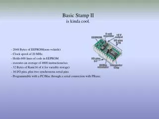
BASIC Stamp 2 (BS2) • The BASIC Stamp 2 (BS2) is an embedded system that includes: • 1. Microcontroller (PIC16C57) – Brains of the system, provides BASIC • interpreter, serial communication, and I/O. • 2. Memory (EEPROM) – User program storage and long term data • storage. • 3. Voltage Regulator – Generates 5Vdc from supply power of 5.5Vdc • to 15Vdc. • Clock – 20MHz resonator. • Miscellaneous Support Components – 4v brown out detector, • transistors, and resistors.
BASIC Stamp 2 microcontroller • PIC16C57 • 8-bit CMOS Microcontroller • RISC CPU (only 33 single word, single cycle instructions) • 28 pin, DIP • 12 bit wide instructions • 8 bit wide data • 8 bit clock counter • 72 bytes of RAM • 1 watch dog timer • 16 I/O pins + 2 dedicated serial • 2K EEPROM/ROM See http://www.microchip.com
BASIC Stamp 2 microcontroller - 2 • PIC16C57 • 16 I/O pins + 2 dedicated serial • 2K EEPROM/ROM • 72 bytes of RAM on PIC • Only 26 bytes available • 20 MHz clock, 4000 instructions per second • 20 mA current (source) limit at each pin (25 mA sink limit) • Caution! • PIC16F84 • Discussed extensively in book • F = flash memory (a type of EEPROM)
BASIC Stamp 2 Memory • Memory (space for code) • 2K Bytes • 500 lines of code • Speed • 20 MHz • 4000 instructions/second • RAM (space for storing variables) • 26 Bytes • REG0 – REG12 are 16-bit registers • 208 1-bit variables (Bits) • 52 4-bit variables (Nibbles) • 26 8-bit variables (Bytes) • 13 16-bit variables (Words) • Program • Stored in EEPROM memory +6 bytes for storing I/O
IMPORTANT: PIN CHARACTERISTICS • Vss (System ground) – Any external circuitry connected to the BS2 • must have a common ground with the BS2. • P0-P15 (general purpose I/O) – Maximum current limits for I/O pins • must be obeyed. • Vdd (5Vdc supply) – If user has 5Vdc available, connect it to this pin. • Vin (5.5Vdc-15Vdc supply) – If user has 5.5-15Vdc, connect it to this • pin. Note that the onboard regulator will step this down to 5Vdc for • use by the BS2 circuitry. MAKE SURE THIS 5Vdc IS NOT USED BY • EXTERNAL CIRCUITRY OR DAMAGE TO THE bs2 WILL OCCUR.
Precautions • Static sensitive device, use grounded wrist strap or touch a grounded • surface before handling the BS2. • Verify power is off before connecting and disconnecting the BS2 and • any external circuitry. • Verify BS2 orientation before inserting it into the carrier board. • Do not overdrive I/O pins, abide by maximum limits. • If using an unregulated supply (5.5-15Vdc), do not drive external • circuitry with the regulated 5Vdc generated by the BS2.
PC to BASIC Stamp 2 • Communicate with the BS2 via the PC serial port (RS232). • Download program from PC to BS2, cannot upload a • program that is already in the BS2. • Can upload data from the BS2 to the PC using the • DEBUG command.
Memory Configuration RAM: - storage of program variables - losses contents at power down - 32 bytes available 6 – I/O pin status 26 – general purpose use EEPROM: - 2K bytes, ~500 instructions - program storage - long term data storage - retains data at power down
Variable Definition Mouse VAR BIT ‘variable can be 0 thru 1 Cat VAR NIB ‘variable can be 0 thru 15 Dog VAR BYTE ‘variable can be 0 thru 255 Rhino VAR WORD ‘variable can be 0 thru 65535 Horse VAR Rhino.BIT9 ‘bit 9 of Rhino Cow VAR Rhino.HIGHBYTE ‘highest 8 bit of Rhino Constant Definition Cheers CON 5
Number Representation • 1 Decimal • $1A6 Hex • %1011 Binary Examples: LetterA CON “A” ‘ASCII code for A (65) Cheers CON 3 ‘decimal Hex128 CON $80 ‘hex FewBits CON %1101 ‘binary
Mathematical Expressions - Addition and Subtraction, order is not important 12+7-3+22=38 22-3+12+7=38 • Multiplication and Division, order is important 12+3*2/4=7 ** 2*12/4+3=9 - Note that the BS2 performs integer math only, as shown in ** 30/4=7 not 7.5 - BS2 solves equations in the order they are written, left to right - Use parenthesis to change order of evaluation 12+((3*2)/4)=13
http://www.parallax.com http://groups.yahoo.com/group/basicstamps/
units in Variable – 2 microseconds maximum pulse width – 131.07milliseconds
units in Period – 2 microseconds maximum pulse width – 131.07milliseconds
units in Cycle – 1millisecond Average voltage – avg. volt.=(Duty/255)*5 Required charge time – 4*R*C