Download
1 / 34
340 likes | 362 Views
Explore waveguide confinement, coupling methods, modulators, and directional coupler equations in optical devices. Learn about directional couplers, Mach-Zehnder modulators, and Bragg modulators using various applications and theories.

E N D
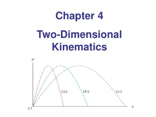
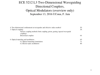
ECE 5212 L3 Two-Dimensional WaveguidingDirectional Couplers, Optical Modulators (overview only) September 13, 2016 UConn, F. Jain 4. Two-dimensional confinement in waveguides and effective index method 50 5. Optical coupling: 58 Various coupling methods (butt coupling, prism, grating, tapered waveguide coupling) Directional couplers 64 6. Optical tunneling and modulators 69 6.1 Optical tunneling formulation 71 6.2 Electro-optic modulators 80
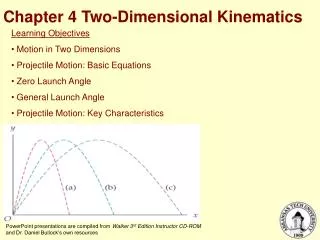
Fig. 7. b-V plot for various TE modes as a function of asymmetry parameter a. [Ref : H.Kogelnik, “Theory of Dielectric Waveguides”, in Integrated optics (Ed. T. Tamir), Publisher: Springer-Verlag 1979.]
Fig. 10. Cross-sectional schematic of various 2-D waveguides. Page-50
Optical coupling: 1. Prism coupler, 2. Grating coupler, 3. Tapered waveguide coupler 4. Directional Couplers, Optical Modulators: 1.Electro-optic modulators using directional couplers, 2. Mach-Zehnder, 3.Electro-absorptive, 4. Electro-optic Fabry-Perot modulators
V V1 V2 1 2 1 2 (a) (b) Substrate electrode (cross-sectional) Three electrode configuration (cross sectional schematic) Overview of Optical Modulators (Pages 81-82 and Chapter 3) 1.Electro-optic modulators using directional couplers, 2. Mach-Zehnder, 3.Electro-absorptive and Electro-optic Fabry-Perot modulators using multiple quantum wells (Chapter 3) 4. Bragg Modulators: electro-optic and acousto-optic Dual channel electro optic modulator using directional couplers use two methods of applying electric field as shown below.
Mach-Zehnder modulator: • It does not use optical tunneling like directional couplers but uses interference effect. The incident beam is divided into two paths and one path’s index of refraction is changed using electro-optic effect. This results in change in the phase of the propagating signal.
Bragg modulators: • Electro-optic grating: It works on diffraction of incident beam by an electro-optic grating. • Acousto-optic grating. Here a surface acoustic wave is launched that sets up a grating which diffracts the incident wave coupled from the left end.
Directional Coupler Equations Two sets of derivations: --one intensive and detailed (pages 71-76 leading to Eqs. 12 and 13. It solves for A(z) and B(z) coefficients (Eqs. 18 page 77) that defines the electric field in two waveguides. Also full power and no power transfer condition Eq. 22 on page 78. The important equation is 25 and 26 (page 79) which determine the coupling length and relate it to index of refraction change. -- Other overview starts from page 85 (Hunsperger material)
n Unperturbed individual guides 1 and 2 (1) n2 n n (2) ncp ncp ncp n n Perturbed when coupling is present w1 s w2 (1) (2)
The length at which coupling power transfer taken place from guide #0 to guide #1 is L and is given by