Download
1 / 28
280 likes | 296 Views
This document provides an overview of the power supplies and electrical utilities for the National Synchrotron Light Source II (NSLS-II) project. It includes design goals, technical specifications, and progress updates on the main dipole and multipole power supplies.

E N D
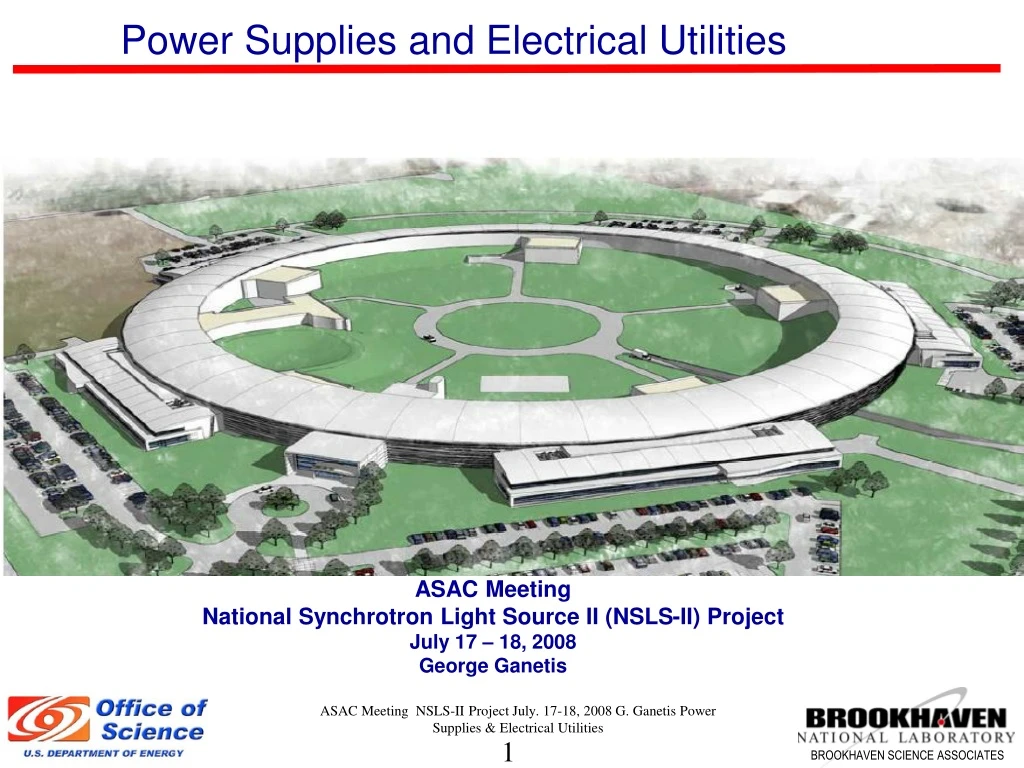
Power Supplies and Electrical Utilities ASAC Meeting National Synchrotron Light Source II (NSLS-II) Project July 17 – 18, 2008 George Ganetis ASAC Meeting NSLS-II Project July. 17-18, 2008 G. Ganetis Power Supplies & Electrical Utilities
Power Supplies, Utilities, & Safety Systems - Outline • Power Supplies • Main Dipole PS • Multipole – Quadrupole & Sextupole PS • Corrector PS • PS Controls • Summary • Electrical & Mechanical Utilities • Equipment Enclosures & Cooling System • Equipment Layout on Mezzanine • Racks and Cable Tray Layouts • AC Power Connections to Accelerator Equipment • Summary ASAC Meeting NSLS-II Project July. 17-18, 2008 G. Ganetis Power Supplies & Electrical Utilities
Design Goals • PS will be designed for very high reliability. • Use of standard commercial power converters where possible. • Minimize custom designs on the power converters. • Minimize connections between ps components. • Use high performance connections between ps components. • Provide a stable and clean environment for the ps. • Design ps to allow fast and easy replacement of any failed components. • Use instrumentation to monitor and track ps performance and the temperature of critical components in each power supply. • PS will have at least a 20 % operating current margin. • PS are located in the equipment area above the tunnel except for certain transport line ps. • The main dipole, quadrupole, sextupole, trim dipole, skew quadrupole power supplies are designed to stay at a fixed current. • Fast global (100 Hz) dipole corrector power supplies will be part of beam-based feedback system. • Electrical Safety • All power supplies will conform to the latest BNL safety requirements, especially concerning arc flash protection. Whenever possible, NRTL-listed equipment will be used. • Arc flash hazard analysis and mitigation will be incorporated in the design efforts ASAC Meeting NSLS-II Project July. 17-18, 2008 G. Ganetis Power Supplies & Electrical Utilities
Power Supplies - Technical Summary ASAC Meeting NSLS-II Project July. 17-18, 2008 G. Ganetis Power Supplies & Electrical Utilities
Power Supplies –Main Dipole • PS Rating - 1200 V 450 A ( Transformer taps can be used to lower voltage ) • Baseline design has two 12-pulse SCR converters that are connected in series with the center point connected to ground. This will reduce the voltage to ground at the magnet load and reduce the voltage rating on various converter components • Each converter will have a two-stage LCRL passive filter and a series pass active filter to reduce the ripple current to low levels. • Combined digital and analog control system with a digital feed forward system. • Technical review committee recommended that the power converters be changed to a switch mode topology. A design study is in progress to do an analysis on this recommendation. • A proto-type digital current regulator is being constructed and will be tested soon. • Baseline wiring diagram is done and procurement specifications for various sub-systems are being drafted. • Mezzanine PS enclosure engineering layout is done. Baseline drawing will done soon. • Large Aperture trim power supply still needs engineering design. ASAC Meeting NSLS-II Project July. 17-18, 2008 G. Ganetis Power Supplies & Electrical Utilities
Power Supplies –Main Dipole ASAC Meeting NSLS-II Project July. 17-18, 2008 G. Ganetis Power Supplies & Electrical Utilities
Multipole Power Supplies –Quadrupole & Sextupole ( TCR ) • Quadrupole circuits will use one power supply for each magnet. • Sextupole circuits will use one power supply for a family of sextupole magnets. There are 9 sextupole families for each pentant. Eight of the families will have 6 magnets ( Except for pentants that have damping wigglers) in it and 1 family will have 12 magnets. There are also 12 circuits with two magnets. There are 4 circuits that are located at each of the three damping wiggler straights. • The power converter section is a commercial voltage-controlled switch-mode design. • Power converter is rated from 3 , 4, & 6.6 kW for the Quads and 3,5, & 10 kW for the Sextupoles. • The power converters fit in a standard 19-inch electronics rack and are only 3.5 to 5.25 inches high. • These power supplies are air-cooled. • Prototype precision analog regulators are in the detailed design phase . • Prototype AC input modules are designed and are being assembled and tested. Procurement specifications and drawing packages are being developed. Informal vendor quotes are in progress. ASAC Meeting NSLS-II Project July. 17-18, 2008 G. Ganetis Power Supplies & Electrical Utilities
Multipole Power Supplies ( TCR ) Detailed 3-D models are being done for each multipole power supply type . ASAC Meeting NSLS-II Project July. 17-18, 2008 G. Ganetis Power Supplies & Electrical Utilities
Multipole Power Supplies ( TCR ) Baseline wiring diagrams are done for all multipole ps and procurement specifications for various sub-systems are being drafted. ASAC Meeting NSLS-II Project July. 17-18, 2008 G. Ganetis Power Supplies & Electrical Utilities
Correctors - Power Supplies ( Baseline ) Fast Global Corrector Power Supplies ( Corrector A) • Four quadrant switch-mode class D amplifier to be incorporated into a bipolar current regulated power supply . This configuration was chosen because of the need for high current for slow alignment and high voltage for bandwidth for beam stability system. Amplifier has a switching frequency of 81 kHz which gives a ripple current of ~ 2 ppm. • Current Reference uses two 18 bit DACs that will have an effective resolution of 20 bits. • Two Prototype power supplies have been constructed and are being tested with a prototype corrector magnet . Transfer function and cross talk measurements are being made. Fast Insertion Corrector Power Supplies( Corrector B) • Four quadrant linear amplifier to be incorporated into a bipolar current regulated power supply. • Current Reference uses a 18 bit DAC Common Features For Both Fast Power Supplies • The power supplies will use a DCCT as the current feedback device • The PSI used for this application will have to a minimum of 10 kHz data transfer rate. • The controls and basic topology are the same as the quadrupole ps except for the PSI and PSC • These power supplies are air-cooled. ASAC Meeting NSLS-II Project July. 17-18, 2008 G. Ganetis Power Supplies & Electrical Utilities
Correctors - Power Supplies ( Baseline ) Alignment Corrector Power Supplies( Corrector D) • The ps is a bipolar, two-quadrant, current-regulated linear design. • The ps uses a linear power amplifier and a switch-mode pre-regulator to minimize the power dissipation in the amplifier. • The pre-regulator is a commercial voltage-controlled switch-mode 1 kW power converter. (33V , 33A) • Current Reference uses a 18 bit DAC .Dipole & Skew Quad Trim Power Supplies ( Corrector C) • Four quadrant linear amplifier to be incorporated into a bipolar current regulated power supply. • Current Reference uses a 16 bit DAC Common Features For Both Fast Power Supplies • The power supplies will use a DCCT as the current feedback device • The controls and basic topology are the same as the quadrupole ps • These power supplies are air-cooled. ASAC Meeting NSLS-II Project July. 17-18, 2008 G. Ganetis Power Supplies & Electrical Utilities
Correctors - Power Supplies ( Baseline ) Baseline wiring diagrams are done for all corrector ps and procurement specifications for various sub-systems are being drafted. ASAC Meeting NSLS-II Project July. 17-18, 2008 G. Ganetis Power Supplies & Electrical Utilities
Correctors - Power Supplies ( Baseline ) Detailed 3-D models are being done for each corrector power supply type . ASAC Meeting NSLS-II Project July. 17-18, 2008 G. Ganetis Power Supplies & Electrical Utilities
Power Supplies –Controls & Instrumentation Controls • Power Supply Controller ( PSC ) will serves as a single channel waveform function generator (wfg), 8 channel transient waveform recorder (twr) and have digital I/O for ps state control and status read-backs. Data transfer rates will be ~ 10 kHz. • The power supply interface ( PSI ) will have 1 or 2 analog outputs ( 16 to 18 bit ) for the current reference , 8 analog input channels that will be used to monitor the ps performance, and 8 digital outputs and 8 digital inputs for ps state control . Data transfer rates will be ~ 10 kHz. • Both PSC and PSI are modified version of an existing BNL design. • A prototype PSI is in the detailed design phase. Instrumentation • Redundant DCCTs will be used to confirm the power supply current reproducibility. • High-precision DMMs and scanners will be used to monitor the ps current, the redundant current sensor, and the analog current set point. This equipment will ensure long-term stability and reproducibility. • Temperature monitoring of the magnet coils and power system environment will be accomplished using low-cost digital (“1-Wire devices”) temperature sensors. • Input current on all ps is measured by low cost digital “1-Wire devices” current sensor. These sensors are built into the AC Input Control Modules • Both temperature sensors and current monitors have been designed and prototypes have been constructed and tested. ASAC Meeting NSLS-II Project July. 17-18, 2008 G. Ganetis Power Supplies & Electrical Utilities
Power Supply - R&D, Summary &Next 12 to 18 Months R&D • Component evaluation tests continue on power supplies, power amplifiers, DCCTs etc. • Test of Corrector A with a magnet load. • R&D continues on ps reliability issues. - Developing ps monitoring instrumentation. Summary • Baseline drawings for the multipole and corrector ps have been completed and procurement specifications have been started. • Technical requirements for the multipole power supplies are maturing. ( TCR ) • More technical details of the system are in the PDR and presentations made to the various design reviews. • Corrector magnet circuits for the insertion region still needs to mature. ( Quantities and location) • Work continues on detailed designs of prototype ps controls and packaging. Next 12 to 18 Months • Design & construction of evaluation prototypes of ps systems. This should in include the PSI, PSC, Reg/Con, and AC input modules. • Finish designs of the physical layout of ps components in the equipment enclosures. • Finish detailed analysis of main dipole ps and make a choice between a switch mode or a SCR converter. • Finish remaining preliminary designs and continue final designs on systems. • Get procurement packages ready - Specifications and SOW ASAC Meeting NSLS-II Project July. 17-18, 2008 G. Ganetis Power Supplies & Electrical Utilities
Electrical Utilities - Equipment Enclosures Equipment Enclosures • All power supplies & equipment will be mounted in sealed NEMA 12 electronics racks, the only exceptions could be for the main dipole ps, safety systems, and booster ps. • Chilled water to air heat exchangers will cool a sets racks. ( ~ 5000 kW cooling capacity per rack ) • Storage ring racks will be located above the magnet tunnel in the equipment area. • 440 racks for day one storage ring , and 40 racks for injection systems • Prototype in-house rack cooling system is designed and constructed and is under testing. • Commercial rack system is being assembled and evaluation testing will start. ASAC Meeting NSLS-II Project July. 17-18, 2008 G. Ganetis Power Supplies & Electrical Utilities
Electrical Utilities - Equipment Enclosures 7 Heater chassis are mounted in each rack that can produce 4.5 kW of heat load per rack. Testing is to see how much heat Can be removed from racks for a given flow of chilled water. Final test will be to install a power supply in the test racks and see how it performs ASAC Meeting NSLS-II Project July. 17-18, 2008 G. Ganetis Power Supplies & Electrical Utilities
Electrical Utilities – Rack Group Layouts Mezzanine Equipment Layout • Racks for all accelerator electrical system have been located on mezzanine. Baseline drawing are being developed for a nominal 3 cell configuration, injection straight, main dipole, & RF straights • Designs includes penetrations into storage ring tunnel through offset conduits. • AC power equipment is also located on the drawings. ASAC Meeting NSLS-II Project July. 17-18, 2008 G. Ganetis Power Supplies & Electrical Utilities
Electrical Utilities – Racks & Cable Tray • Detailed 3-D models are being develop with equipment racks , cable tray, offset conduits, and • tunnel equipment. • Large effort spent to develop interface information for conventional facilities. • Wiring spreadsheets are being developed for all accelerator systems and detailed wiring schedules • are being developed. • Models are being used to develop detailed plan view drawings for cable trays, and detailed length • values for system cables. ASAC Meeting NSLS-II Project July. 17-18, 2008 G. Ganetis Power Supplies & Electrical Utilities
Electrical Utilities –AC Power Connections AC Power Connections • Route equipment power from the load panels provided by conventional facilities to the electrical loads • This includes the cable tray, conduit, AC input power cable, AC power switches, and all associated components. • Designs will minimize arc flash hazards. Have done equipment research for motorized circuit breakers for 480 circuits. • Instrumentation will be used monitor temperature, current, voltages in critical components. • Base lined one line AC power diagrams are done for typical mezzanine storage ring cell, injection straight, main dipole power supply, linac–booster service bldg, RF service bldg. , cryo plant bldg. , and pentant water system pumps. • Continue to update detailed spreadsheet that identifies all accelerator and experimental electrical loads. ASAC Meeting NSLS-II Project July. 17-18, 2008 G. Ganetis Power Supplies & Electrical Utilities
Electrical Utilities – AC Power Connections One line diagram for typical mezzanine storage ring cell ASAC Meeting NSLS-II Project July. 17-18, 2008 G. Ganetis Power Supplies & Electrical Utilities
Electrical Utilities – Special AC Power Equipment Special AC Power Equipment • AC power equipment includes UPS (uninterruptible power supplies) and/or AC line conditioning equipment. ( 30 kVA UPS planed for every cell for critical controls ) • Design includes distribution panels and service transfer switches. • Baseline one line AC power diagrams have included UPS systems. • Engineering evaluation of UPS systems will take place at the end of this FY. ASAC Meeting NSLS-II Project July. 17-18, 2008 G. Ganetis Power Supplies & Electrical Utilities
Electrical Utilities–R&D, Summary, Next 18 Months R&D • R&D work continues on testing the chilled water to air heat exchangers. • Build up of a complete set of racks and instrument it to measure thermal performance. Summary • Base line drawings are being developed for mezzanine accelerator electrical equipment. • Base line one line diagrams have been developed for most of accelerator systems. • Detailed wiring and cable tray plan being engineered. Next 18 Months • Finish Thermal performance measurements of racks. • Finish preliminary designs and continue final designs . • Get procurement packages ready - Specifications and SOW ASAC Meeting NSLS-II Project July. 17-18, 2008 G. Ganetis Power Supplies & Electrical Utilities
Backup Slide- Electrical Utilities Offset Conduit Layout – Top View looking Through the Storage Ring Tunnel Ceiling Dipole Magnet Tunnel Cable Tray Equipment Rack on Mezzanine Equipment Rack on Mezzanine Offset Conduit ASAC Meeting NSLS-II Project July. 17-18, 2008 G. Ganetis Power Supplies & Electrical Utilities
Backup Slide- Electrical Utilities Example of a Design Study for Cable Penetration in the Injector Complex Storage Ring Injection Straight Booster Ring Cable Tray Conduit Injection Systems Service Bldg. ASAC Meeting NSLS-II Project July. 17-18, 2008 G. Ganetis Power Supplies & Electrical Utilities
Backup Slide- Electrical Utilities Rack layouts are done to ensure there is sufficient rack space on the mezzanine ASAC Meeting NSLS-II Project July. 17-18, 2008 G. Ganetis Power Supplies & Electrical Utilities
Backup Slide- Electrical Utilities ASAC Meeting NSLS-II Project July. 17-18, 2008 G. Ganetis Power Supplies & Electrical Utilities
Backup Slide- Corrector Power Supply Corrector Power Supplies Coil to Measure Frequency Response of the magnetic Field 100 mm Corrector Magnet ASAC Meeting NSLS-II Project July. 17-18, 2008 G. Ganetis Power Supplies & Electrical Utilities