Download
1 / 18
190 likes | 419 Views
Magnetic Measurements for PACMAN Marco Buzio, TE/MSC/MM. Contents 1 – Rotating coils 2 – Stretched wire. Main PACMAN WP 2.2 goal

E N D
Magnetic Measurementsfor PACMAN Marco Buzio, TE/MSC/MM Contents 1 – Rotating coils 2 –Stretched wire
Main PACMAN WP 2.2 goal Development of a rotating coil system (single scanning coil and/or coil train) integrated on the PACMAN test stand in bldg. 169 and aimed at field quality (strength, harmonics, direction) measurements of CLIC quadrupoles. Magnetic measurement of the axis: if possible absolute, otherwise in relative (fixed-coil) mode with ultra-high bandwidth and resolution.This implies, within the 3-years span: a dedicated FAME system with an optimized PCB coil(s), FDI, FFMM script etc…. Metrological qualification, cross-checks with other instruments, with documented calibration and test procedures
Search coils • Workhorse of CERN instrumentation park: most accurate and cost-effective method • Size, effective surface, number of turns, resistance, assemblies … must be adapted to the specific requirements of each magnet no commercial solution, in-house R&D • Main parameter: total area exposed to flux change Ac, which determines the peakinduced voltage (limited by electronics, typically 5 or 10 V) fixed-coil,time-varying field coil rotating, translatingor deforming (wire) Faraday’s law (total derivative) Fixed coil in a time-varying field Coil rotating at angular speed in stationary, uniform field Coil translating at speed v in stationary field with gradientB
Rotating coils • Rotating coils: yield simultaneously field strength, quality (harmonics), direction and center 2D ideal rectangular rotating coil geometry integration constant: lost with fixed coil measurements,irrelevant (unphysical) for rotating coils integration boundsset by precise angular encoder rotation speed fluctuationshave negligible effects measured flux depends on both the fieldand coil geometry Discrete sampling of flux → Fourier components → field harmonics
Rotating coil types • Tangential coils: • higher signal for the same area (on the boundary of the convergence circle) • blind spot, difficult to align precisely • Radial coils • easier to build and to calibrate • sensitive to all harmonics
Coil sensitivity factors • All coefficients can be calculated from coil length L, width w and radius R0 • All coefficients proportional to total coil area Ac=NTLw • All coefficents increase like radius R0n-1 NB: calibration coefficients can be used at any field level – inherently linear sensor However: S/N at calibration gets better at high field
Why is it difficult to measure small-aperture magnets ? e.g.: radial coil, n>1 • general problem: static and dynamic deformations, vibrations, alignment, temperature drifts are more difficult to control • Mechanical manufacturing tolerances are fixed=f(tooling) → coil sensitivity coefficient uncertainty 1/r (r=outer rotation radius) • the number of turns available for coils (→ signal level) r2 • Signal level grow with linked flux variation → rn-1 (e.g. radial coil), rn (stretched wire)(field/gradient strength, rotation/translation speed, length, etc. being equal) S/N ratio for quadrupole measurement may vary with r3 r4 …. BUT: small magnets are easier to flip around …
Coil bucking • The accuracy of higher harmonics measured by individual coils may be affected by geometry errors • Solution = coil bucking (or compensation): suitable linear combinations of coil signals cancel out the sensitivity to the main (and lower) harmonics robustness to mechanical imperfections • Example: in a perfect quadrupole, average gravity-induced sag on a radial coil flux error including mainly B1 and B3 components. A four-coil series/anti-series combination cancels out B2 sensitivity error-free harmonic measurement B A d C D () ideal geometry(no sag) C A • Arbitrary static coil imperfections cause no concern (effective sensitivities can be calibrated) • Position- or time-dependent transversal imperfectionserrors harmonic n=main order • Position- or time-dependent torsional imperfections errors harmonic n=main order -1 • Coil design objective: main=main-1=0, maximize |n| with n>main order • Additional benefit: common mode rejection, improved S/N (requires separate amplification) flux error()(zoomed) sag-inducedvertical eccentricity B D
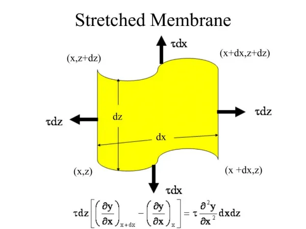
Effective coil width • The flux corresponding to a given coil position can be obtained in various ways (flipping or rotating the coil, pulsing the field from zero) • L can be considered as known from mechanical measurements • General case: unless B(s) or w(s) are constant and can be taken out of the integral sign, the flux cannot be obtained from average width and average field: • Define: effective width (NT gets lumped in for convenience) = average of width weighted with the field considerations made here for a dipole field hold true for other components as well
Linac4 harmonic coil test bench • Developed for small-aperture Linac4 permanent-magnet and fast-pulsed quads • Æ19 mm, 200~400 mm long quadrupole-bucked coils (difficult measurement: S/N µÆaperture3 !) • Harmonic measurements in DC (continuously rotating coil) or fast-pulsed (stepwise rotating) mode. • small size flipping the magnet around allows elimination of many systematic errors • in-situ calibration technique to improve accuracy despite geometrical coil imperfections
Innovative miniature coils for CLIC quadrupoles CLIC QD0 prototype 64-layer PCB stack 3-coil dipole- and quadrupole- bucked arraycan be chained to measure long magnets at once
PCB coil-related R&D themes • general improvement of multi-layer PCB coils: track density (currently only ~1/3 of conventional coils), layer referencing and alignment (currently ~0.1 mm) • optimization of track layout to minimize sensitivity to production errors • improvement of the existing 8 mm rotating PCB coil shaft: mechanical stiffness of the assembly (materials, geometry, resins …), alignment and stability of ball bearings, scaling above and below 8 mm (e.g. is it possible 4 mm for CLIC, 20 mm for Linac magnets, or even more ?) • development (as suggested by Stephan) of a more compact Mini Rotating Unit MRU-II, i.e. about 10-12 contacts instead of the current 76, better adapted to small coils, with less angular vibrations • PCB-based quench antennas (with compensation) • micro PCB connectors for multi-strand wire coils (as suggested by Olaf, to replace the existing micro-soldered connectors that only Lucette knows how to make) • large scale PCB fluxmeters: upper limits of current printing, pressing and assembly techniques + new possibilities offered by ELTOS; alternative architectures e.g. multiple mass-produced short boards + suitable inter-board connections • quality assurance of PCB fluxmeters: AC measurement of coil width, R/L measurement, calibration of magnetic equivalent coil area and coil distance inside reference magnets • micron-level precision coils for high order analog bucking (e.g. integrated circuit - scale fluxmeters) • Joe di Marco-style, polyvalent PCB sandwich coil shaft (flexible design, may be very practical for very large diameter rotating systems). Advanced materials (foams, honeycombs etc … for higher stiffness-to-weight ratio) • electronic acquisition systems: correction of side effects of high resistance load coils (input impedances, automatic resistance measurement and off-line correction, noise and offsets) • software tool to facilitate the design of new PCB coils, bypassing traditional CAD: from geometry specifications (e.g. straight/arc/straight or more realistic continuously varying curve) layer design Gerber format file • other techniques alternative to PCB: circuits printed on flexible rolls, inkjet circuit printers
Single Stretched Wire B stage A stage Reference quadrupole
Classical Single Stretched Wire • DC operation: nominal fieldlevel • AC operation: enhanced sensitivity at very low field levels (e.g. 1 A in LHC cryomagnets),elimination of DC offset (stray fields, remanent …) S0, pitch, yaw iterativeaxis finding field harmonics Gxdy, Gydxfield direction (roll)
A stage B stage As tension measurement is affected by friction problems and gauge accuracy, the SSW system measures the fundamental frequency of the wire, which depends uponh its mechanical properties
Magnetic properties of the wire Integrated Strength (Gdl) (5) • Four different wires have been tested: • 0.1mm CuBe wire from California Fine Wire Co, USA • 0.1mm Mg wire from California Fine Wire Co, USA • 0.13mm CuBe wire from Goodfellow Co, UK • Carbon fiber strand from TohoTenaz Europe gmbh, type HTA5241 • (5). ( 0.078mm silicon carbide, type SCS-9A from Speciality Materials Co, USA) • (Note: type 5. could not be magnetically tested because of its high rigidity) SCS-6 Silicon Carbide CuBe Carbon fiber HTA5241 Different type of tested wire Slopes of strength for different types of wire in [T/s2] • Note: • if strength rises when tension increases, wire is diamagnetic • If strength falls when tension increases, wire is paramagnetic IMMW14