Download
1 / 23
230 likes | 580 Views
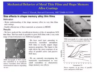
A study of Thin Film Shape Memory Alloys. By Rajlakshmi Purkayastha Metallurgical and Materials Science IIT Bombay. Shape Memory Alloys. Shape memory alloys (SMAs) are metals that "remember" their original shapes.

E N D
A study of Thin Film Shape Memory Alloys By Rajlakshmi Purkayastha Metallurgical and Materials Science IIT Bombay
Shape Memory Alloys • Shape memory alloys (SMAs) are metals that "remember" their original shapes. • SMAs are useful for such things as actuators which are materials that "change shape, stiffness, position, natural frequency, and other mechanical characteristics in response to temperature or electromagnetic fields" • The potential uses for SMAs especially as actuators have broadened the spectrum of many scientific fields. • The study of the history and development of SMAs can provide an insight into a material involved in cutting-edge technology. • The diverse applications for these metals have made them increasingly important and visible to the world.
Shape Memory Effect • The Shape Memory effect refers to the fact that after a sample of SMA has been deformed from its "original" conformation, it regains its original geometry by itself during heating (one-way effect) or, at higher ambient temperatures, simply during unloading (pseudo-elasticity or superelasticity). • SME is the ability to return to a previously defined shape through appropriate thermal procedure after being severely deformed.
Those crystal structures are known as martensite and austenite. • These extraordinary properties are due to a temperature-dependent martensitic phase transformation from a low-symmetry to a highly symmetric crystallographic structure.
Thin Films • Shape memory alloys (SMA’s) possess an array of desirable properties: • high power to weight (or force to volume) ratio, thus the ability to recover large transformation stress and strain upon heating and cooling, • peudoelasticity (or superelasticity), • high damping capacity, • good chemical resistance and biocompatibility, etc. • This attracted much attention to the research of SMAs as smart (or intelligent) and functional materials. • More recently, thin film SMA has been recognized as a promising and high performance material in the field of micro-electro-mechanical system (MEMS) applications, since it can be patterned with standard lithography techniques and fabricated in batch process.
Why thin films? • Thin films have a wide variety of applications. Thus an analysis of the stress – strain behaviour of these films becomes very important to analyse, and predict their beahaviour under different conditions. • The main factors that affect the behaviour of these films are: • Temperature • Materials Used • Stress Applied
Temperature Dependance • The transformation from Austenite to Martensite and vice-versa is temperature Dependant • The temperatures at which the SMA changes its crystallographic structure are characteristic of the alloy, and can be tuned by varying the elemental ratios. • Typically, Ms denotes the temperature at which the structure starts to change from austenite to martensite upon cooling. Mf is the temperature at which the transition is finished. • Accordingly, As and Af are the temperatures at which the reverse transformation from martensite to austenite start and finish, respectively.
Materials Used • Each Material is different in terms of: • Transformation Temperature • Youngs Modulus and other Material constants • The most common and important alloy used is Nitinol – composed of Nickel and Titanium • Other examples include Indium thallium , Nickel Aluminium Magnesuim
Stress Applied • Stress can be applied in two Directions – biaxial stress or in only one direction – uniaxial stress • Rather than measuring the stress applied, it is easier to measure the strain caused, and calculate stress using Hookes law Stress = [elastic coeff]*strain • Phase transformations can also be brought about by the application of stress rather than change in temperature
Mechanics of thin films deposited on substrate • The major three reasons for biaxial stresses in thin films are thermal strains, growth strains, and epitaxial strains. • In general thermal strains are the result of thermal expansion coefficient mismatch between the substrate and the thin film equation (1) shows this effect (1) ε=−∆α∗∆T • The film is free to move in the z direction only, as it is constrained by the substrate in the y and x direction • The transformation and subsequent stress equations are modelled on this fact. • Thus a solution to a very real problem, thermally induced stress, is sought.
The problem • These variants have different orientations. • What we have to do is analyse and detemine the volume fractions of each of the variants formed in a phase transformation , due to applied stress in a thin film. • When austenite transforms into martensite it transforms into different variants • The number of variants depends on the crystal structure. For example a tetragonal system has three variants whilst a monoclinic (check) has 12 variants.
Methodology • The problem is solved using Energy Minimisation • We know that the film will transform in such a way so as to minimise the total stress energy. • We therefore calculate the total energy due to the formation of these variants and then use a standard optimisation routine with set boundary conditions to calculate the volume fraction of each variant.
The details…. • In this problem we are analysing a biaxial stress applied to a thin film of In-23%Th, i.e. an Indium-Thallium Shape Memory Alloy • It is a Cubic-Tetragonal transformation. • There are three variants of Martensite formed • Assumptions • We assume that there is no change in temperature during the transformation • We assume that all of the austenite is transformed into Martensite i.e. there is no retained austenite. • All material constants are kept fixed throughout the transformation.
Results • On running the optimisation routine for equal strains applied in both x and y direction, we get the following graph • The graph shows that the energy clearly reaches a minimum at v2 = v3 = 0.5, when v1 = 0.0
The adjacent graph shows the variation of the minimum. The minimum keeps on shifting to the right as the value of v1 increases, but is always reached at a point where v2 = v3. • Also, note that as v1 increases, the total energy increases, making the system more unstable. Thus the system is most stable at minimum v1 i.e. v1 = 0.0
...when unequal strains are applied… • The variants are formed in different ratios in order to accommodate the varying strain. • The equations used are the same, but will change for energy calculation due to symmetry considerations
The two graphs below show the change in the variants due to the unequal stress. Again, V1 is varied from 0.1 to 1.0 The variation of Energy with V2 shows that all the variant forms tends to be V2 The variation of Energy with V3 shows that energy minimisation occurs at V3 -> 0.
Conclusion • In an ideal situation, the maximum variant fraction formed depends on the direction in which the stress is applied. • When strains are equally applied, then fractions of V2 and V3 are the same • When unequal strains are applied, the maximum variant formed is in the direction of the larger strain.
Acknowledgement I would sincerely like to thank my guide for this project, Prof Prita Pant, for giving me this opportunity to work with her. It has been a very good learning experience, indeed. I would also like to mention the IRCC Summer Fellowship Programme, under whose aegis this work was carried out Thank You
Basic Equations… • et = (I – U1)*v1 + (I – U2)*v2 + (I-U3)*v3 • e0 =strain applied • et = strain due to phase transformation • Ui = Transformation Matrix in the ‘i’th Direction • I = Identity Matrix • Now, we assume that the body is allowed to move freely in the ‘z’ direction as it perpendicular to both of the applied stresses and is normal to the plane of the substrate. • With this in mind, the applied strain in the z-direction is taken to be e* , and is calculated using the stress relationship.
Therefore ,eapp = [ e* 0 0 0 e0 0 0 0 e0 ] • Thus, e = eapp – et • E = s*e where, s = stress, e = strain, E = energy • s = e*C , where C = stress transformation Coefficient Matrix • Thus, E = e*C*e • Boundary conditions are: • v1 + v2 + v3 = 1 • v1,v2,v3r 0 • v1,v2,v3b 1