Download
1 / 1
10 likes | 163 Views
Grips. Vibration Control. Force Verification. Protocol.

E N D
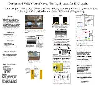
Grips Vibration Control Force Verification Protocol A protocol was created for the validation of the creep testing system to provide a consistent method for the testing of materials, following ASTM standards. The protocol is divided into manageable sections including Test Specimen Dimensions, Test Specimen Fabrication, Grip Maintenance, Force Calibration, Vibration Control, Data Collection, and Reporting of Data as seen in greater detail below. Previously: Currently: mg T Figure: Force body diagram of the creep testing system while undergoing force verification with the spring. Hooke’s law, F = -kx was used to determine the spring constant, k. Figure: Graph of Force (lb.) vs. Displacement of the spring from 6 grams to 24 grams with 2 gram increments. Spring constant of 0.0348 lb/in, 1.2% error. Figure : The previous top grip has two components of force in the longitudinal direction. Figure : The current top grip has a single force in the longitudinal direction. Figure: Picture of the creep testing system with the granite block beneath it. A 12”x12”x4” granite block polished on both sides was purchased for absorbing bench-top vibrations. -kx LVDT • Bottom and top grip clamp surfaces were sanded and lined with adhesive rubber and sand paper to minimize slippage of samples. LVDT The Samples IPN Samples: Legend: • G = Gelatin • PEGdA = polyethylene glycol diacrylate • 600 = 600 MW PEG • 2k = 2k MW PEG • All solution ratios are given in weight % • All formulations are 10% Gelatin 4 Formulations Room Temperature PBS Solution pH 7.4 +/- 0.1 40G/60PEGdA600 40G/60PEGdA2k 50G/50PEGdA600 50G/50PEGdA2k Creep Testing External Weight • Must maintain constant weight • Can apply weight slowly and evenly • Must not enter LVDT core • Light weight • Durable • Fits onto existing • weight rack • Counter weight compensation Sample Fabrication The Mold: Teflon® Reusable Mold Future Work • Meets ASTM dimensions • Easy to fabricate • Teflon® is inexpensive and molds are reusable • Add method to change temperature of chamber • Vary stresses for each sample type • Test formulations containing a modified gelatin backbone • Test formulations containing modified PEGdA Figure 7: The Teflon® mold is sandwiched between glass slides to keep the thickness consistent. The IPN is fabricated between them. Aknowledgements Conclusions • Christy Palmer • Kao Lab • Glennys Mensing PhD • WJ Kao PhD • IPNs containing 600MW PEGdA under went more creep than 2k samples. • Formulations containing 600MW underwent more creep at lower gelatin/PEGdA ratios • The creep chamber is capable of testing various formulations of IPNs consistently Marking Gauge Length At this step, food coloring is used to mark a set gauge length on the IPN Design and Validation of Creep Testing System for Hydrogels. Team: Megan Toth& Kelly Williams, Advisor: Glennys Mensing, Client: Weiyuan John Kao, University of Wisconsin-Madison, Dept. of Biomedical Engineering. Abstract Interpenetrating networks (IPNs) have many biomedical applications such as wound healing. The efficacy of the IPN as a wound dressing is dependent on its mechanical properties. A creep testing system coupled with an environmental chamber was previously designed to evaluate the tensile creep properties of the IPNs. The goal of this project is to validate the pre-existing device following ASTM standard D2990 while modifying the device design and the test specimen fabrication protocol for improvements. A protocol was written to validate each component of the entire system. The protocol was followed to test three latex samples as standards and three IPN samples. LVDT Verification Figure: Image of the current design. The current design is composed of: an acrylic chamber, a pair of grips, counterbalance, granite block, a weight rack, an extensometer (LVDT), an analog to digital converter, and a computer for data acquisitioning. Background • Interpenetrating Networks (IPNs) • Composed of cross-linked gelatin and poly(ethylene glycol) diacrylate • Used as a wound dressing To verify the extensometer, the LVDT core was marked and measured manually at 6 distances, while being held in that position. These measurements were compared with the output from the LVDT in Microsoft Excel from the WinDaq software. Motivation • Creep testing of IPNs: • Provides mechanical strength characteristics • Mimics tensile stress on IPNs due to wound contraction Figure 8: IPN Testing Results. The average test results are shown for each formulation tested with an n = 3. Tests were conducted for three hours in PBS at room temperature and pH of 7.4. Problem Statement Table 1: IPN Raw Testing Data. Data for all three trials of each of four formulations are given. This data corresponds to the graph in Figure . • Modify existing protocol and creep testing system to provide optimal experimental conditions. • Test different formulations of IPNs in an 11 week study. Design Specifications • Temperature: +/- 2oC • pH: constant pH • Force: +/- 1% of applied load • Specimen Dimensions: • 11 mm gage length • 2 mm gage width • 1 mm thickness Counterweight Previously:Aluminum Cylinder Currently:Lead Slip Shots • Did not account for the buoyant force of the top grip • Accounts for the buoyant force of the top grip • Mass is evenly distributed along wire