Download
1 / 17
170 likes | 275 Views
Ensure subscribers have ideal signal levels to prevent singing, echo, and reflection issues in the network. Learn about volume objectives, loudness rating, stability considerations, and echo delay management. Explore loss factors, attenuation requirements, and echo effects.

E N D
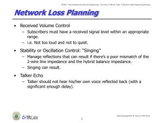
Network Loss Planning • Received Volume Control • Subscribers must have a received signal level within an appropriate range. • i.e. Not too loud and not to quiet. • Stability or Oscillation Control: “Singing” • Manage reflections that can result if there’s a poor mismatch of the 2-wire line impedance and the hybrid balance impedance. • Singing can result. • Talker Echo • Talker should not hear his/her own voice reflected back (with a significant enough delay).
Volume Objectives • Reference Equivalent (RE) or Overall R. E. (ORE) • A measure of perceived loudness of the signal. • ITU in Geneva used group of telephone users to judge loudness. • Measured by adjusting an attenuator in a simulated network. • Rated “highest tolerable volume”, “preferred volume” and “lowest tolerable volume”. • Results showed that attenuator settings of <6dB were too loud and >21dB were too faint.
Mouth to Interface Loss Interface to Interface Loss Interface to Ear Loss Overall Loudness Rating (OLR) • New standard circa 1990. • Loss accumulated from speaker’s mouth and listener’s ear. • OLR = SLR + CLR + RLR SLR – Send Loudness Rating CLR – Circuit Loudness Rating RLR – Receive Loudness Rating OLR Good/Excellent Poor/Bad 5-15dB 90% 1% 20dB 80% 4% 25dB 65% 10% 30dB 45% 20%
Amplifier transmit receive 2-wires 2-wires Hybrid Hybrid 2-wires 2-wires 2-wires 2-wires receive transmit Amplifier Reflection (ZB ZL) Stability • Long distance connections all have 2-W to 4-W to 2-W conversion (as do most local connections). • If there’s a poor mismatch of the 2-W line impedance with the hybrid balance impedance, signal energy passes across the hybrid reflecting from one 4-W direction into the other.
Minimum return loss seen at the hybrid in any frequency in the voice-band Ideal loss Loss in practice (~3.5 db splitting loss) Stability (2) • Reflection at the hybrid re-inserts the signal with “balance return loss” (BRL or BS) into the return side of the 4-W loop. Additional 3+dB loss at hybrid when converting 4-W signal to 2-W signal, and another 3+dB going from 2-W to 4-W (6db total). Total trans-hybrid loss of returned signal:
Net Gain of one side of 4-W loop (total amplifier gain minus line losses) G 3dB BS+6dB 3dB T 2-W to 2-W total attenuation Stability (3)
Stability (4) • Total round-trip closed loop loss (“singing margin”): Generally found to be adequate if: • Otherwise, singing may result. • out of control runaway oscillation in the loop. • can continue even after the original impulse ceases.
Stability (5) • Loss in a 4-W circuit may depart from its nominal value for a number of reasons: • Variation in line losses and amplifier gain with time, temperature, etc. • Gain or loss will differ at different frequencies (usually tested at 800 Hz and/or 1600 Hz). • Measurement errors. • Circuit errors.
Variance of trans-hybrid loss Variance of gain or loss in each 4-W section Number of 4-W sections Recall: 3 standard deviations from the mean is equivalent to 0.1% Recall: We have singing if m = 2(T+BS) < 6dB 3Tot 0.1% 6dB 2(T+BS) Stability (6) • Define new term for variance of round trip loss: What if we want only 0.1% chance of singing?
Stability (7) Typical values: This is basis for a generally accepted approximation or rule of thumb for 99.9% chance of stability (i.e. no singing):
Stability (8) • Example: We have a long distance circuit with 6 4-W sections. What is the minimum attenuation (T) required for a 99.9% chance of not singing?
Talker Listener Be+6dB T Talker Echo: Listener Echo: Echo-Delay • If the reflection at the hybrid is strong enough, telephone users will hear it. • Talker echo is when talker hears his/her own voice. • Listener echo is when listener hears talker’s voice twice. Loss = Be + 2T Loss = 2Be + 2T
B(f) Return Loss at Frequency f Be (echo) BS (stability) Frequency Echo-Delay (2) • Recall Bs: • Balance Return Loss • Minimum return loss seen at any voice-band frequency • What is Be? • Hybrid Echo Return Loss • Average return loss in voice-band. Why Be and not BS?
Echo-Delay (3) • Subjective annoyance of echo depends on relative echo level and on the delay. • The stronger the echo and the longer the delay, the more troublesome the echo. One-Way Delay Loss to Satisfy 50% 10 ms 11.1 dB 20 ms 17.7 dB 30 ms 22.7 dB 40 ms 27.2 dB 50 ms 30.9 dB
Echo-Delay (4) • The echo objective is for 99% of all connections to have acceptable or better echo effects. • Factors to consider: • Be = Expected hybrid echo return loss. • Be = Standard deviation of Be • T = Nominal 2W-2W loss in connection. • T = Standard deviation of T • Ē(t) = E = Expected echo attenuation for delay t at which 50% of users find echo tolerable. • E = Standard deviation of E
Mean margin against objectionable echo M has a standard deviation: 2.33M 1% 0 E Echo-Delay (5) • For the connection to be acceptable, we want: What if we want a 99% chance of acceptable echo? Recall: 2.33 std. dev. from the mean is equivalent to 1%