Download
1 / 36
360 likes | 536 Views
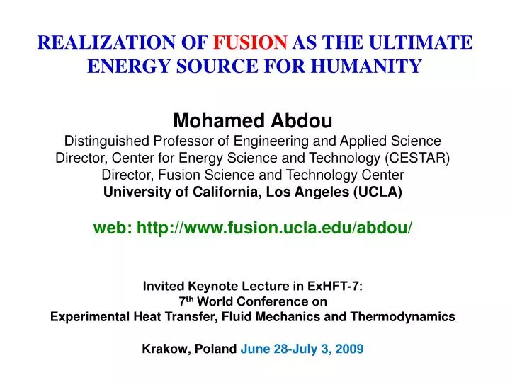
REALIZATION OF FUSION AS THE ULTIMATE ENERGY SOURCE FOR HUMANITY. Mohamed Abdou Distinguished Professor of Engineering and Applied Science Director, Center for Energy Science and Technology (CESTAR) Director, Fusion Science and Technology Center University of California, Los Angeles (UCLA)

E N D
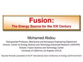
REALIZATION OF FUSION AS THE ULTIMATE ENERGY SOURCE FOR HUMANITY Mohamed Abdou Distinguished Professor of Engineering and Applied Science Director, Center for Energy Science and Technology (CESTAR) Director, Fusion Science and Technology Center University of California, Los Angeles (UCLA) web: http://www.fusion.ucla.edu/abdou/ Invited Keynote Lecture in ExHFT-7: 7th World Conference on Experimental Heat Transfer, Fluid Mechanics and Thermodynamics Krakow, Poland June 28-July 3, 2009
REALIZATION OF FUSION AS THE ULTIMATE ENGERGY SOURCE FOR HUMANITY OUTLINE • Fusion Research Transition and DEMO Goal • ITER • Blanket Principles and Interactions • MHD Thermofluid Issues • Blanket Types and Issues • Science-based framework for FNST Development • Blanket Testing in ITER • Need for a New Fusion Nuclear Facility • Summary
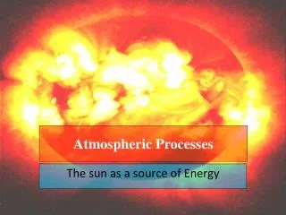
What is fusion? Fusion powers the Sun and Stars. Two light nuclei combine to form a heavier nuclei (the opposite of nuclear fission). Deuterium and tritium is the easiest, attainable at lower plasma temperature, because it has the largest reactionrate and high Q value. The World Program is focused on the D-T Cycle Used to breed tritium and close the DT fuel cycle Li + n → T + HeLi in some form must be used in the fusion system Deuterium 80% of energy release (14.1 MeV) E = mc217.6 MeV Neutron Helium Tritium 20% of energy release (3.5 MeV) Illustration from DOE brochure
Incentives for Developing Fusion • Sustainable energy source (for DT cycle: provided that Breeding Blankets are successfully developed and tritium self sufficiency conditions are satisfied) • No emission of Greenhouse or other polluting gases • No risk of a severe accident • No long-lived radioactive waste • Fusion energy can be used to produce electricity and hydrogen, and for desalination.
Fusion Research is about to transition from Plasma Physics to Fusion Science and Engineering • 1950-2010 • The Physics of Plasmas • 2010-2035 • The Physics of Fusion • Fusion Plasmas-heated and sustained • Q = (Ef / Einput )~10 • ITER (magnetic fusion) and NIF (inertial fusion) • 2010-2040 ? • Fusion Nuclear Science and Technology for Fusion • DEMO by 2040? • > 2050 ? • Large scale deployment!
The World Fusion Program has a Goal for a Demonstration Power Plant (DEMO) by ~2040(?) Plans for DEMO are based on Tokamaks Poloidal Ring Coil Cryostat Coil Gap Rib Panel Blanket Maint. Port Plasma Vacuum Vessel Toroidal Coil Center Solenoid Coil (illustration is from JAEA DEMO Design)
ITER • The World has started construction of the next step in fusion development, a device called ITER. • ITER will demonstrate the scientific andtechnological feasibility of fusion energy for peaceful purposes. • ITER will produce 500 MW of fusion power. • Cost, including R&D, is ~15 billion dollars. • ITER is a collaborative effort among Europe, Japan, US, Russia, China, South Korea, and India. ITER construction site is Cadarache, France. • ITER will begin operation in hydrogen in ~2019. First D-T Burning Plasma in ITER in ~ 2026
~29 m ITER ITER is a reactor-grade tokamak plasma physics experiment - a huge step toward fusion energy • Will use D-T and produce neutrons • 500MW fusion power, Q=10 • Burn times of 400s • Reactor scale dimensions • Actively cooled PFCs • Superconducting magnets ~15 m • By Comparison, JET • ~10 MW • ~1 sec • Passively Cooled JET
Magnet System in Tokamak (e.g. ITER) has 4 sets of coils • 18 Toroidal Field (TF) coils produce the toroidal magnetic field to confine and stabilize the plasma • Superconducting, Nb3Sn/Cu/SS • Max. field: 11.8T • 6 Poloidal Field (PF) coils position and shape the plasma • Superconducting, NbTi/Cu/SS • Max. field: 6T • Central Solenoid (CS) coil induces current in the plasma • Superconducting, Nb3Sn/Cu/alloy908 • Max. field: 13.5T • 18 Correction coils correct error fields • Superconducting, NbTi/Cu/SS • Max. field < 6T TF coil case provides main structure of the magnet system and machine core Stored energy in ITER magnetic field is large ~ 1200 MJ Equivalent to a fully loaded 747 moving at take off speed 265 km/h
China Europe India Japan (w/EU) South Korea U.S. EAST JT-60SA (also LHD) KSTAR W7-X (also JT-60SA) SST-1 New Long-Pulse Confinement and Other Facilities Worldwide will Complement ITER ITER Operations: 34% Europe 13% Japan 13% U.S. 10% China 10% India 10% Russia 10% S. Korea Being planned Fusion Nuclear Science &Technology Testing Facility (FNSF/CTF/VNS)
Blanket Radiation Plasma Neutrons The primary functions of the blanket are to provide for: Power Extraction & Tritium Breeding Shield Vacuum vessel DT First Wall Magnets Coolant for energy extraction Tritium breeding zone Lithium-containing Liquid metals (Li, PbLi) are strong candidates as breeder/coolant
Fusion Nuclear Science and Technology(FNST) Fusion Power & Fuel Cycle Technology FNST includes the scientific issues and technical disciplines as well as materials, engineering and development of fusion nuclear components: From the edge of Plasma to TF Coils: 1. Blanket Components (includ. FW) 2. Plasma Interactive and High Heat FluxComponents (divertor, limiter, rf/PFC element, etc) 3. Vacuum Vessel & Shield Components The location of the Blanket inside the vacuum vessel is necessary but has major consequences: a- many failures (e.g. coolant leak) require immediate shutdown b- repair/replacement take long time
Fusion environment is unique and complex:multi-component fields with gradients • Neutron and Gamma fluxes • Particle fluxes • Heat sources (magnitude and gradient) • Surface (from plasma radiation) • Bulk (from neutrons and gammas) • Magnetic Field (3-component) • Steady field • Time varying field • With gradients in magnitude and direction Plasma Width (for ST) B BT Inner Edge 0 R Outer Edge Bp Multi-function blanket in multi-component field environmentleads to: • Multi-Physics, Multi-Scale PhenomenaRich Science to Study - Synergistic effectsthatcannotbe anticipated from simulations & separate effects tests. Modeling and Experiments are challenging
Challenging Fusion Nuclear Science & Technology Issues • Tritium Supply & Tritium Self-Sufficiency • High Power Density • High Temperature • MHD for Liquid Breeders / Coolants • Tritium Control (Extraction and Permeation) • Reliability / Maintainability / Availability • Testing in Fusion Facilities
Flows of electrically conducting coolants will experience complicated MHD effects in the magnetic fusion environment 3-component magnetic field and complex geometry Motion of a conductor in a magnetic field produces an EMF that can induce current in the liquid. This must be added to Ohm’s law: Any induced current in the liquid results in an additional body force in the liquid that usually opposes the motion. This body force must be included in the Navier-Stokes equation of motion: For liquid metal coolant, this body force can have dramatic impact on the flow: e.g. enormous MHD drag, highly distorted velocity profiles, non-uniform flow distribution, modified or suppressed turbulent fluctuations. Dominant impact on LM design. Challenging Numerical/Computational/Experimental Issues 16
MHD Characteristics of Fusion Liquid Breeder Blanket Systems
Net JxB body force p = VB2 tw w/a - For high magnetic field and high speed (self-cooled LM concepts in inboard region) the pressure drop is large - The resulting stresses on the wall exceed the allowable stress for candidate structural materials Perfect insulators make the net MHD body force zero But insulator coating crack tolerance is very low (~10-7). It appears impossible to develop practical insulators under fusion environment conditions with large temperature, stress, and radiation gradients Self-healing coatings have been proposed but none has yet been found (research is on-going) Self-Cooled liquid Metal Blankets are NOT feasible now because of MHD Pressure Drop A perfectly insulated “WALL” can solve the problem, but is it practical? Conducting walls Insulated walls Lines of current enter the low resistance wall – leads to very high induced current and high pressure drop All current must close in the liquid near the wall – net drag from jxB force is zero 18 Impact of MHD and no practical Insulators :No self-cooled blanket option
Separately-cooled LM BlanketExample: PbLi Breeder/ helium Coolant with RAFM EU mainline blanket design All energy removed by separate Helium coolant The idea is to avoid MHD issues. But, PbLi must still be circulated to extract tritium ISSUES: Low velocity of PbLi leads to high tritium partial pressure , which leads to tritium permeation (Serious Problem) Tout limited by PbLi compatibility with RAFM steel structure ~ 470 C (and also by limit on Ferritic, ~550 C) Possible MHD Issues : MHD pressure drop in the inlet manifolds B- Effect of MHD buoyancy-driven flows on tritium transport Module box(container & surface heat flux extraction) Breeder cooling unit (heat extraction from PbLi) Stiffening structure (resistance to accidental in-box pressurization i.e He leakage) • Drawbacks: Tritium Permeation and limited thermal efficiency He collector system (back) 19
DCLL Typical Unit Cell Self-cooled Pb-17Li Breeding Zone SiC FCI He-cooled steelstructure Pathway Toward Higher Temperature through Innovative Designs with Current Structural Material (Ferritic Steel):Dual Coolant Lead-Lithium (DCLL) FW/Blanket Concept • First wall and ferritic steel structure cooled with helium • Breeding zone is self-cooled • Structure and Breeding zone are separated by SiCf/SiC composite flow channel inserts (FCIs) that • Provide thermal insulation to decouple PbLi bulk flow temperature from ferritic steel wall • Provide electrical insulation to reduce MHD pressure drop in the flowing breeding zone FCI does not serve structural function Pb-17Li exit temperature can be significantly higher than the operating temperature of the steel structure High Efficiency
High pressure drop is only one of the MHD issues for LM blankets; MHD heat and mass transfer are also of great importance! FCI overlap gaps act as conducting breaks in FCI insulation • Instabilities and 3D MHD effects in complex detailed geometry and configuration with magnetic and nuclear fields gradients have major impact. • Unbalanced pressure drops (e.g. from insulator cracks) leading to flow control and channel stagnation issues • Unique MHD velocity profiles and instabilities affecting transport of mass and energy • Accurate Prediction of MHD Heat &Mass Transfer is essential to addressing important issues such as: • thermal stresses, • temperature limits, • failure modes for structural and functional materials, • thermal efficiency, and • tritium permeation. and hence disturb current flow and velocity, and redistribute energy Courtesy of Munipalli et al. 21 (Ha=1000; Re=1000; =5 S/m, cross-sectional dimension expanded 10x)
Buoyancy effects in DCLL blanket DCLL DEMO blanket, US Caused by and associated • Can be 2-3 times stronger than forced flows. Forced flow: 10 cm/s. Buoyant flow: 25-30 cm/s In buoyancy-assisted (upward) flows, buoyancy effects may play a positive role due to the velocity jet near the “hot” wall, reducing the FCI T In buoyancy-opposed (downward) flows, the effect may be negative due to recirculation flows Effect on the interface T, FCI T, heat losses, tritium transport Vorticity distribution in the buoyancy-assisted (upward) poloidal flow
Corrosion Is A Serious Issue For LM Blankets • At present, the interface temperature between PbLi and Ferritic Steel (FS) is limited to < 470 C because of corrosion • This is very restrictive and does not allow higher temperature operation with FS or advanced ODS. • Data available are from corrosion experiments with no magnetic field. They are static or dynamic. • Results show strong dependence on temperature and on the velocity of PbLi. • Therefore, corrosion should be expected to experience MHD effects due to sharp changes in the velocity and temperature profiles. • There is experimental evidence of the effect of magnetic field. • Criteria for determining the allowable interface temperature : a) thinning of the walls (in the “hot” section) due to corrosion b) deposition of the corrosion products transported in the heat transport loop to the Heat Exchanger (“cold” section) causing radioactive “CRUD” that hampers HX maintenance. c) corrosion products deposition in the “cold” section causing clogging small orifices, valves, etc. Usually the criterion c) is applied with the assumption, that the corrosion rate has to be limited to 20 micron/year in order to avoid clogging. This leads to an allowable interface temperature of ~ 470 C as measured in experiments with turbulent flow without magnetic fields • Experiments with sodium loops have shown that deposits in the "cold" sections is more limiting than thinning of the "hot" walls Hence, in addition to corrosion rates, it is important to predict the behavior of the corrosion products in the entire heat transport loop, particularly “deposition”.
Experiments in Riga (funded by Euratom) Show Strong Effect of the Magnetic Field on Corrosion (Results for PbLi in Ferritic Steel) Macrostructure of the washed samples after contact with the PbLi flow B=0 T B=1.8 T Strong experimental evidence of significant effect of the applied magnetic field on corrosion rate. The underlying physical mechanism has not been fully understood yet From: F. Muktepavela et al. EXPERIMENTAL STUDIES OF THE STRONG MAGNETIC FIELD ACTION ON THE CORROSION OF RAFM STEELS IN Pb17Li MELT FLOWS, PAMIR 7, 2008
Need R&D on Corrosion: Modelling and Experiments in MHD Flows Relevant to the Fusion System Environment • Corrosion includes many physical mechanisms that are currently not well understood (dissolution of the metals in the liquid phase, chemical reactions of dissolved non-metallic impurities with solid material, transfer of corrosion products due to convection and thermal and concentration gradients, etc.). • We need to better understand corrosion process, including transport and deposition. • We need new models that can predict corrosion rates and transport and deposition of corrosion products throughout the heat transport system. • These models need to account for MHD velocity profiles and heat transfer in the blanket and the temperature gradients and complex geometry in the entire heat transport systems. • More comprehensive experiments are needed. • Need to simulate MHD velocity profiles • Need to simulate the temperature field and temperature gradients in the “hot” and “cold” sections. • Better instrumentation • R&D to develop corrosion resistant “barriers” will have high pay off. • Highest interest is in PbLi systems with both ferritic steel and SiC (FCI).
Illustration of Coupling between MHD and heat and mass transfer in blanket flows MHD Flow Heat Transfer Mass Transfer Buoyanoy-driven flows Convection Diffusion Tritium transport Corrosion He Bubbles formation and their transport Dissolution, convection, and diffusion through the liquid Dissolution and diffusion through the solid Deposition and aggregation Transport of corrosion products Interfacial phenomena Tritium Permeation Coupling through the source / sink term, boundary conditions, and transport coefficients
Science-Based Framework for FNST R&D involves modeling and experiments in non-fusion and fusion facilities Theory/Modeling/Data Design Codes Basic Separate Effects Multiple Interactions Partially Integrated Integrated Component Design Verification & Reliability Data • Fusion Env. Exploration Property Measurement Phenomena Exploration • Concept Screening • Performance Verification Non-Fusion Facilities (non neutron test stands, fission reactors and accelerator-based neutron sources) Testing in Fusion Facilities • Experiments in non-fusion facilities are essential and are prerequisites to testing in fusion facilities • Testing in Fusion Facilities is NECESSARY to uncover new phenomena, validate the science, establish engineering feasibility, and develop components
MHD flows in fusion context are characterized by very unique effects not seen in ordinary fluid dynamics MTOR Thermofluid/MHD facility at UCLA Liquid metal free surface flow experiment Magnetic field suppresses short wavelength surface oscillations and consolidates them into larger surface disturbances aligned with the field Ying (UCLA) 1 m/s flow, B = 0 B = 1.2 T • High interaction parameter ~103 to 105(ratio Magnetic / Inertial Forces) • Inertia forces are small compared with electromagnetic forces, except in some thin layers • Result: Joule dissipation associated with the strong magnetic field induces a strong flow anisotropy, ultimately leading to a quasi-2D state.
Fusion plasma facing components must survive for long operating time with severe heat fluxes PMTF-1200 high heat flux facility at SNL High heat flux experiments Repeated high heat flux and thermal cycle survivability tests on mockups of the first wall for ITER, both EU (right column) and US (left column) samples survived 12,000 cycles at 0.875 MW/m2 and 1000 cycles at 1.4 MW/m2 (Ulrickson, SNL) Fusion heat flux requirements rival that of rocket engines, but must operate for long periods of time Effects of thermal cycling are particularly worrisome for ITER operation, where many pulses of the burning plasma are required Slide 29
Irradiation experiments in fission reactors to test tritium release/retention in lithium ceramics Ceramic breeder irradiation experiments Unit cells of Beryllium and Li4SO4 have been tested in the NRG reactor in Petten, Netherlands to investigate tritium release characteristics and combine neutron and thermomechanical damage to ceramic breeder and beryllium pebble beds Using lithium bearing ceramics is one option, often in the form of small pebble beds But this material must release tritium and resist damage by neutrons and extreme thermal conditions Fission experiments are being used to explore this behavior prior to testing in fusion
Testing Blankets in the fusion environment is Necessary: Combined effects of Radiation, Surface Heat flux, Nuclear Heating & gradients, Magnetic field & gradients, etc can be reproduced only in a fusion facility. PbLi flow is strongly influenced by MHD interaction with plasma confinement field and buoyancy-driven convection driven by spatially non-uniform volumetric nuclear heating This MHD flow and convective heat transport processes determine the temperature and thermal stress of SiC FCI The FCI temperature and thermal stress coupled with early-life radiation damage effects in ceramics affect deformation,cracking, and properties of the FCI Cracking and movement of the FCIs will strongly influence MHD flow behavior by opening up new conduction paths that change electric current profiles Example: MHD flow & FCI behavior are highly coupled in a complex fusion environment Simulation of 2D MHD turbulence in PbLi flow Courtesy of S. Smolentsev FCI temperature, stress and deformation Resulting temperature field also strongly couples to phenomena such as tritium transport and permeation, and corrosion 31 31
Equatorial Port Plug Assy. Port Frame TBM Assy ITER Provides Substantial Hardware Capabilities for Testing of Blanket System He pipes to TCWS TBM System (TBM + T-Extrac, Heat Transport/Exchange…) Bio-shield • ITER has allocated 3 ITER equatorial ports (1.75 x 2.2 m2) for TBM testing • Each port can accommodate only 2 modules (i.e. 6 TBMs max) A PbLi loop Transporter located in the Port Cell Area 2.2 m Vacuum Vessel Fluence in ITER is limited to 0.3MW-y/m2 . We have to build another facility, for FNST development
THREEStages of FNST Testing in Fusion Facilities are Required Prior to DEMO D E M O Role of FNF (CTF/VNS) Role of ITER TBM Component Engineering Development & Reliability Growth Engineering Feasibility & Performance Verification Fusion “Break-in” & Scientific Exploration Stage III Stage I Stage II 1 - 3 MW-y/m2 > 4 - 6 MW-y/m2 0.1 - 0.3 MW-y/m2 1-2 MW/m2, steady state or long pulse COT ~ 1-2 weeks 1-2 MW/m2, steady state or long burn COT ~ 1-2 weeks 0.5 MW/m2, burn > 200 s Sub-Modules/Modules Modules/Sectors Modules • ITER is designed to fluence < 0.3MW-y/m2.ITER can do only Stage I • A Fusion Nuclear Facility, FNF is needed , in addition to ITER, to do Stages II (Engineering Feasibility) and III (Reliability Growth) • FNF must be small-size, low fusion power (< 150 MW), hence, a driven plasma with Cu magnets.
Example of Fusion Nuclear Facility (FNF) Device Design Option :Standard Aspect Ratio (A=3.5) with demountable TF coils (GA design) • High elongation, high triangularity double null plasma shape for high gain, steady-state plasma operation • Challenges for Material/Magnet Researchers: • Development of practical “demountable” joint in Normal Cu Magnets • Development of Inorganic Insulators (to reduce inboard shield and size of device)
Lessons learned:The most challenging problems in FNST are at theINTERFACES • Examples: • MHD insulators • Thermal insulators • Corrosion(liquid/structure interface temperature limit) • Tritium permeation • Research on these interfaces must integrate the many technical disciplines of fluid dynamics, heat transfer, mass transfer, thermodynamics and material properties in the presence of the multi-component fusion environment (must be done jointly by blanket and materials researchers)
Summary Fusion is the most promising long-term energy option renewable fuel, no emission of greenhouse gases, inherent safety The blanket must simultaneously achieve tritium breeding and power extraction at high temperature in a multi-component fusion environment (magnetic field, radiation field, surface heat flux, bulk heating) with strong gradients. This results in new phenomena and synergistic effects that can not be anticipated from simulations and separate-effect tests. Fluid dynamics, heat & mass transfer play important role in R&D for blankets and other plasma-facing components. Other important disciplines are neutronics, radiation effects, structural mechanics. LM Blankets are most promising, but their potential is limited by MHD effects. Innovative concepts must continue to be proposed and investigated Modeling and experiments for blanket and PFC are challenging because of complex geometry, multi component fields with gradients, and the inability to simulate bulk heating in the lab without neutrons. Significant progress has been made in 3-D modeling and in laboratory experiments. 7 nations started construction of ITER to demonstrate the scientific and technological feasibility of fusion energy. ITER will have first DT plasma in ~2026 The most challenging Phase of Fusion development still lies ahead. It is the development of Fusion Nuclear Science and Technology (FNST) ITER, limited fluence, addresses only initial Stage of FNST testing In addition to ITER, a Fusion Nuclear Facility (FNSF) is required to develop FNST. 36 36