Download
1 / 82
830 likes | 1.11k Views
FPGA: From Flashing LED to Reconfigurable Computing. Wu, Jinyuan Fermilab IIT Mar, 2009. Outline. Electronic Aspect of FPGA: LED Flashing Logic Elements in a Nutshell TDC and ADC FPGA as a Computing Fabric: Moore’s Law Forever? Space Charge Computing with FPGA Cores

E N D
FPGA: From Flashing LED to Reconfigurable Computing Wu, Jinyuan Fermilab IIT Mar, 2009 Wu Jinyuan, Fermilab jywu168@fnal.gov
Outline • Electronic Aspect of FPGA: • LED Flashing • Logic Elements in a Nutshell • TDC and ADC • FPGA as a Computing Fabric: • Moore’s Law Forever? • Space Charge Computing with FPGA Cores • Doublet Matching & Hash Sorter • Triplet Matching & Tiny Triplet Finder • Enclosed Loop Micro-Sequencer (ELMS) Wu Jinyuan, Fermilab jywu168@fnal.gov
Flashing LED, The First Thing First Counter Q[23..0] • At least design an LED for an FPGA. • When a board is first powered up, first test the LED flashing function. • Many things have to be right so that the LED flashes: • Power pins must be all connected. • Configuration devices must be in correct mode. • Design software must be correct. Wu Jinyuan, Fermilab jywu168@fnal.gov
LUT Counter A Q[23..0] A<B B LED Brightness Variation Counter A Q[23..0] A<B • The LED brightness is varied by changing the output pulse duty-cycle. • Comparator input A is the brightness and B is the clock cycle count. • Look-up table can be added to input A for different brightness variation curve. B Wu Jinyuan, Fermilab jywu168@fnal.gov
DAC Input A A>B Counter B Q Duty-Cycle Based Single-Pin DAC (1) • The duty-cycle or pulse width of the comparator output is proportional to the DAC input at port A. • Use external RC as low-pass filter. • Output voltage of an ideal LP filter is proportional to the DAC input. Wu Jinyuan, Fermilab jywu168@fnal.gov
LED Brightness Exponential Drop if (CO==1) {Q = Q - Q/32;} S(-) SET D Q • Narrow pulse are typically stretched for LED display with fix brightness. • The circuit here provides gradually dim of the LED for better visual effect. A A<B Counter CO B Q Wu Jinyuan, Fermilab jywu168@fnal.gov
Exponential Sequence Generator if (CO==1) {Q = Q - Q/32;} S(-) SET D Q Possible Student Lab • An exponential sequence is generated using an accumulator shown above. • Note that not even one multiplier is used. • Other function sequences: sine, co-sine, tangent, co-tangent etc. can also be generated similarly. Wu Jinyuan, Fermilab jywu168@fnal.gov
S CO DAC Input D Q Duty-Cycle Based Single-Pin DAC (2) Possible Student Lab • Use carry-out of the accumulator as the output. • The number of pulses is proportional to the DAC input. • Rounding error is carried to later cycles. • Output is smoother. Wu Jinyuan, Fermilab jywu168@fnal.gov
Outline • Electronic Aspect of FPGA: • LED Flashing • Logic Elements in a Nutshell • TDC and ADC • FPGA as a Computing Fabric: • Moore’s Law Forever? • Space Charge Computing with FPGA Cores • Doublet Matching & Hash Sorter • Triplet Matching & Tiny Triplet Finder • Enclosed Loop Micro-Sequencer (ELMS) Wu Jinyuan, Fermilab jywu168@fnal.gov
D D Q Q ENA ENA CLRN CLRN Logic Elements A B C D LUT4 (16 RAM Cells) Normal Mode: LUT4 + DFF LUT = Look-Up Table CI A LUT3 8 Cells Arithmetic Mode: 2 x LUT3 + DFF LUT3 8 Cells B CO Wu Jinyuan, Fermilab jywu168@fnal.gov
“Any” 4-in Functions What Can Be Done With a Lookup Table A B C D Wu Jinyuan, Fermilab jywu168@fnal.gov
D Q ENA CLRN Xilinx Look-Up Table 16-bit Distributed RAM RAM16 16-bit Shift Register SRL16 LUT4 4-input Look-Up Table Wu Jinyuan, Fermilab jywu168@fnal.gov
D D D Q Q Q ENA ENA ENA CLRN CLRN CLRN Pipeline Structure LUT4 (16 RAM Cells) LUT4 (16 RAM Cells) LUT4 (16 RAM Cells) LUT4 (16 RAM Cells) Logic cells are usually designed in pipeline structures. Wu Jinyuan, Fermilab jywu168@fnal.gov
D D Q Q ENA ENA CLRN CLRN Logic Element as a Full Adder Bit CI A LUT3 8 Cells LUT3 8 Cells B A LUT3 8 Cells LUT3 8 Cells B A Logic cell resembles a full adder bit. CO Wu Jinyuan, Fermilab jywu168@fnal.gov
Myths on FPGA • We commonly heard about FPGA: • FPGA is cheap. • FPGA is fast. • FPGA is large. • FPGA can do anything. • Not really, at least it is not always the case. • The reality is: • FPGA is ultra-flexible. • As the cost of the flexibility, the transistor usage in FPGA is NOT efficient. • Good design tricks are needed. Wu Jinyuan, Fermilab jywu168@fnal.gov
4-Input NAND, 4-Input NOR, 4-Input NAOR 8 transistors each A B C D A B C D A B C D Y Y Y A B C D A C A B B D Y C Y A In ASIC D B Y C C D A B C D D A B Wu Jinyuan, Fermilab jywu168@fnal.gov
D Q ENA CLRN Transistor Usage of Logic Element At least 96 transistors LUT 16-bit X 16 6-transistor RAM bit In FPGA Wu Jinyuan, Fermilab jywu168@fnal.gov
A B B A B Ci B A A Ci Sb Ci Cob Ci A A B A B A B Ci B The Mirror Adder (Weste93) In ASIC 24-28 transistors Wu Jinyuan, Fermilab jywu168@fnal.gov
Full Adder CI A S D Q B CO D Q ENA CLRN Full Adder At least 96 transistors LUT 8-bit LUT 8-bit In FPGA Wu Jinyuan, Fermilab jywu168@fnal.gov
Other FPGA Resources • Other resources are available in FPGA devices: • RAM Blocks • Multipliers • Serial Data Receivers, Power PC, etc. Multipliers RAM Blocks 16 Logic Elements Wu Jinyuan, Fermilab jywu168@fnal.gov
Outline • Electronic Aspect of FPGA: • LED Flashing • Logic Elements in a Nutshell • TDC and ADC • FPGA as a Computing Fabric: • Moore’s Law Forever? • Space Charge Computing with FPGA Cores • Doublet Matching & Hash Sorter • Triplet Matching & Tiny Triplet Finder • Enclosed Loop Micro-Sequencer (ELMS) Wu Jinyuan, Fermilab jywu168@fnal.gov
TDC Using FPGA Logic Chain Delay • This scheme uses current FPGA technology • Low cost chip family can be used. (e.g. EP2C8T144C6 $31.68) • Fine TDC precision can be implemented in slow devices (e.g., 20 ps in a 400 MHz chip). IN CLK Wu Jinyuan, Fermilab jywu168@fnal.gov
Two Major Issues In a Free Operating FPGA • Widths of bins are different and varies with supply voltage and temperature. • Some bins are ultra-wide due to LAB boundary crossing Wu Jinyuan, Fermilab jywu168@fnal.gov
Auto Calibration Using Histogram Method • It provides a bin-by-bin calibration at certain temperature. • It is a turn-key solution (bin in, ps out) • It is semi-continuous (auto update LUT every 16K events) 16K Events DNL Histogram S LUT In (bin) Out (ps) Wu Jinyuan, Fermilab jywu168@fnal.gov
The Test Module Data Output via Ethernet FPGA with 8ch TDC Two NIM inputs BNC Adapter to add delay @ 150ps step. Wu Jinyuan, Fermilab jywu168@fnal.gov
As good as ASIC TDC Test ResultNIM Inputs RMS 10ps 140ps 0 1 2 Wave Union TDC B BNC adapters to add delays @ 140ps step. Wave Union TDC B + NIM/ LVDS Wave Union TDC B Wave Union TDC B - LeCroy 429A NIM Fan-out Wave Union TDC B NIM/ LVDS Wave Union TDC B + Wave Union TDC B Wu Jinyuan, Fermilab jywu168@fnal.gov Wave Union TDC B
Clock Domain Changing Multi-Sampling TDC FPGA Multiple Sampling Q3 QF c0 c0 QE Q2 • Ultra low-cost: 48 channels in $18.27 EP2C5Q208C7. • Sampling rate: 360 MHz x4 phases = 1.44 GHz. • LSB = 0.69 ns. c90 QD Q1 c180 Q0 c90 c270 DV T0 T1 Trans. Detection & Encode 4Ch Coarse Time Counter TS Logic elements with non-critical timing are freely placed by the fitter of the compiler. This picture represent a placement in Cyclone FPGA Wu Jinyuan, Fermilab jywu168@fnal.gov
V1 V1 V3 V3 V2 V2 V4 V4 T1 T1 T2 T2 T3 T3 T4 T4 FPGA ADC Using FPGA AMP & Shaper ADC AMP & Shaper ADC • Analog signals from AMP & Shapers are directly fed to FPGA pins. • FPGA outputs and passive RC network are used to generate ramping reference voltage VREF. • The input voltages and VREF are compared using FPGA differential input receivers. • The times of transitions representing input voltage values are digitized by TDC blocks in FPGA. AMP & Shaper ADC AMP & Shaper ADC FPGA AMP & Shaper TDC AMP & Shaper TDC AMP & Shaper TDC AMP & Shaper TDC VREF R1 R1 C R2 Wu Jinyuan, Fermilab jywu168@fnal.gov
ADC Test: Waveform Digitization on BD3_19 FPGA TDC TDC Possible Student Lab VREF 50 50 Input Waveform, Overlap Trigger & Reference Voltage 1000pF 100 Raw Data Converted Wu Jinyuan, Fermilab jywu168@fnal.gov
Outline • Electronic Aspect of FPGA: • LED Flashing • Logic Elements in a Nutshell • TDC and ADC • FPGA as a Computing Fabric: • Moore’s Law Forever? • Space Charge Computing with FPGA Cores • Doublet Matching & Hash Sorter • Triplet Matching & Tiny Triplet Finder • Enclosed Loop Micro-Sequencer (ELMS) Wu Jinyuan, Fermilab jywu168@fnal.gov
Moore’s Law • Number of transistors in a package: x2 /18months Taken from www.intel.com Wu Jinyuan, Fermilab jywu168@fnal.gov
Status of Moore’s Law: an Inconvenient Truth • # of transistors • Yes, via multi-core. • Clock Speed • ? Taken from www.intel.com Wu Jinyuan, Fermilab jywu168@fnal.gov
The Fever of Moore’s Law vs. Maxwell’s Equations Op/sec WRW MIT, 2002 1998 2000 2002 2004 2006 2008 2010 • During the hot days of Moore’s Law, the rules of thumb are: • BRB – Buy Rather than Build • URU – Use Rather than Understand • WRW – Wait Rather than Work • From fundamental principles like Maxwell’s Equations, it is known limits of Moore’s Law exist. The technology advance comes from hard work. Wu Jinyuan, Fermilab jywu168@fnal.gov
The Execution & Non-Execution Cycles From MIT 6.823 Open Course Site • In current micro-processors: • Each instruction takes one clock cycle to execute. • It takes many clock cycles to prepare for executing an instruction. • Pipelined? Yes. But the non-execution pipeline stages consume silicon area, power etc. • To execute an instruction != to do useful calculation. • Can we do something different? Wu Jinyuan, Fermilab jywu168@fnal.gov
Outline • Electronic Aspect of FPGA: • LED Flashing • Logic Elements in a Nutshell • TDC and ADC • FPGA as a Computing Fabric: • Moore’s Law Forever? • Space Charge Computing with FPGA Cores • Doublet Matching & Hash Sorter • Triplet Matching & Tiny Triplet Finder • Enclosed Loop Micro-Sequencer (ELMS) Wu Jinyuan, Fermilab jywu168@fnal.gov
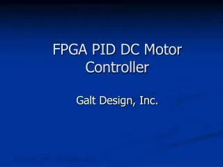
The Space Charge Computing • Each electron sees sum of Coulomb forces from other N-1 electrons. • The total number of calculations is about N2 and each calculation of the Coulomb force requires a square root, a division and several multiplications. • Regular sequential computers are not fast enough. Wu Jinyuan, Fermilab jywu168@fnal.gov
The FPGA Board • Up to 16 FPGA devices ($32 ea) can be installed onto each board. • Each FPGA host one core. Wu Jinyuan, Fermilab jywu168@fnal.gov
xj yj zj - X xi - X yi - X zi vyj vzj vxj x2 LUT 10b in 16b out + S S S + + + + x2 + + 32-bit Forces 16-bit Velocities 16-bit Coordinates x2 The 16-bit Demo Core Wu Jinyuan, Fermilab jywu168@fnal.gov
x2 x2 + x2 The Lookup Table LUT 10b in 16b out Wu Jinyuan, Fermilab jywu168@fnal.gov
Two Electrons with Natural Scales 256 nm 28ps Wu Jinyuan, Fermilab jywu168@fnal.gov
256 Charged Particles, Iteration 0 Wu Jinyuan, Fermilab jywu168@fnal.gov
256 Charged Particles, Iteration 5 Wu Jinyuan, Fermilab jywu168@fnal.gov
256 Charged Particles, Iteration 10 Wu Jinyuan, Fermilab jywu168@fnal.gov
256 Charged Particles, Iteration 15 Wu Jinyuan, Fermilab jywu168@fnal.gov
256 Charged Particles, Iteration 20 Wu Jinyuan, Fermilab jywu168@fnal.gov
256 Charged Particles, Iteration 25 Wu Jinyuan, Fermilab jywu168@fnal.gov
256 Charged Particles, Iteration 30 Wu Jinyuan, Fermilab jywu168@fnal.gov
256 Charged Particles, Iteration 35 Wu Jinyuan, Fermilab jywu168@fnal.gov
256 Charged Particles, Iteration 40 Wu Jinyuan, Fermilab jywu168@fnal.gov
Speed Comparison with Regular CPU • The FPGA core is x10 faster than a typical 2.2 GHz CPU core. • The FPGA core runs at 200 MHz or 200 M Coulomb force calculations/s. • It seems the CPU core needs 80-100 clock cycles for each Coulomb force calculation. Wu Jinyuan, Fermilab jywu168@fnal.gov