HWRF Initialization Overview
140 likes | 323 Views
HWRF v3.5a Tutorial College Park, MD, January 14, 2014. HWRF Initialization Overview. Ligia Bernardet NOAA ESRL Global Systems Division, Boulder CO University of Colorado CIRES , Boulder CO. This talk gives an overview of Atmos pre-processing Data assimilation Vortex Improvement.

HWRF Initialization Overview
E N D
Presentation Transcript
HWRF v3.5a Tutorial College Park, MD, January 14, 2014 HWRF Initialization Overview Ligia Bernardet NOAA ESRL Global Systems Division, Boulder CO University of Colorado CIRES , Boulder CO
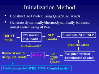
This talk gives an overview of • Atmos pre-processing • Data assimilation • Vortex Improvement First part of talk: tail-Doppler radar is not available and data assimilation is performed only in the 27-km domain.
Global data from GDAS and GFS is used for IC/BC Data Assimilation Vortex Adjustment Forecast model
Preliminary ICs for d01 use the 6-h forecast of the 6-h GDAS. • E.g., 12 UTC HWRF uses 6-h forecast of the 06 UTC GDAS, valid at 12 UTC. • Initial conditions use GDAS spectral coefficients, on GDAS native vertical levels (binary format). Since WPS cannot process this use prep_hybrid tool. • The lower boundary information (soil T, q; topography, etc.) is obtained from the GRIB GDAS file through WPS. • Preliminary ICs generated using real.
The wrfinput_d01 is modified through data assimilation using GSI. When inner core data assimilation is not performed, GSI is only run on d01.
Two triple-domain 90-s WRF runs are used to downscale the d01 data to 9- and 3-km grids. Boundary conditions for these runs are obtained from the 9-h forecast of the 6-h previous GFS. The WRF analysis run uses the same domains as the HWRF forecast run. The WRF ghost run used a larger 3-k domain. The ghost domain is used when inner core data assimilation is performed. Here it is just a place holder.
The downscaled, high-resolution, initial conditions conditions are further modified by the vortex initialization. If adjusts the location, intensity, and structure of the vortex according to current observations (TCVitals).
After the vortex adjustment, the various domains need to be reconciled, or merged, to generate the final ICS.
The boundary conditions (wrfbdy) are created from the GFS forecast .
Second part of talk: tail-Doppler radar is available and data assimilation is performed in 27-km and 3-km domains Order is reversed: DA is performed after vortex initialization
Same figure as before, except DA does not appear. It is performed AFTERWARDS.
t = -3 h t = +3 h t = 0 h Because the TDR data spans a window in time (takes a while for plane gather data)… Must create analyses at t-3h and t+3h, so GSI can interpolate analyses to obs time Therefore, repeat procedure 3 times (except LBC for forecast only created once)
Two runs of GSI are performed (27- and 3- km), each ingesting 3 time levels Results are merged to create initial conditions
Upcoming talks In the next talks, you will learn more about • The Community GSI package • How GSI was customized for HWRF • The algorithm used for vortex initialization