Download
1 / 50
500 likes | 644 Views
Boosting Your Knowledge of… TURBO- CHARGING . Randy Knuteson – Analytical / Air Safety. 1905 – Patent by Dr. Alfred J. Buchi. Historical Perspective:. 1905 – Sulzer Bros. designs first turbo. 1910 – G.E. begins manufacturing turbos 1915 – First turbo diesel engine.

E N D
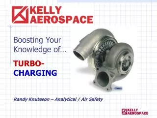
Boosting Your Knowledge of… TURBO-CHARGING Randy Knuteson – Analytical / Air Safety
Historical Perspective: 1905 – Sulzer Bros. designs first turbo • 1910 – G.E. begins manufacturing turbos • 1915 – First turbo diesel engine 1918 – Dr. Sanford Moss altitude tests a 350 hp turbocharged engine.
Historical Perspective: 1920 – New altitude record in a LePere Bi-Plane – 33,113 feet!
Historical Perspective: 1921 – John Macready's flight to 40,800' in an open cockpit Lusac 11, Lepere biplane.
Turbo-Supercharged B-36 Six 28-Cylinder Engines Without Turbos – 90 Cylinders per Engine!
ENGINE HORSEPOWER DEPENDS ON… • …The amount of fuel and air an engine burns. • …The density of the charge, not the volume. So…actual power is determined by the MASS of air consumed.
PRINCIPLES OF TURBOCHARGING Sea-level air density = 0.0765 lb. cu. ft. At 10,000 ft. air density = 0.0565 lb. cu. ft. A Naturally-Aspirated Engine 100 hp @ sea-level = 73.9 hp @ 10,000 ft.
WHY TURBOCHARGE? • Power diminishes with an increase in altitude. • Gain more power and increase engine efficiency without enlarging the powerplant. • Recapture the heat energy normally wasted out the exhaust. GOAL – Convert Exhaust Energy into Manifold Pressure
A TURBOCHARGER IS AN… …“AIRPUMP” powered by the unused heat energy normally wasted out the exhaust.
Routing of exhaust and compressor discharge air Filteredambient air inlet Compressor outlet Spent exhaust gases overboard Exhaust gas inlet (T.I.T.) from the combustion process
1650° F As high as 125,000 RPMs!
TURBOCHARGING DEFINITIONS • Turbocharging BOOSTED– HP increase (31-45”MAP) • Turbo-Normalizing NORMALIZED – Maintains sea-level performance (29.5” MAP) at altitude.
Upper Deck Pressure From compressor discharge to the throttle plate. Manifold Pressure From the throttle plate to the cylinder intake port. TURBOCHARGING DEFINITIONS
Sludge build-up in the “wedge” can decrease the oil pressure feeding into the bearing and shaft
30-60 PSI Piston rings keep air and exhaust pressures out of the center housing
TURBO COMPONENTS:COMPRESSOR STAGE(Cold Side) Discharge Air Volute shape – converts velocity energy into pressure energy
Power increase MAP increases Exhaust volume increases TURBO “RUN-AWAY” COULD EXCEED MAXIMUM ENGINE OPERATING LIMITS! Increased compressor discharge Turbo begins to spin faster
Decrease power MAP decreases Decreased exhaust flow Compressor discharge decreases Turbo slows down
4 BASIC SYSTEM COMPONENTS • Turbocharger • Controller • Wastegate • Absolute Pressure Relief Valve (PRV)
4 BASIC SYSTEM COMPONENTS Aneroid Bellows Upper Deck Pressure Oil restrictor Valve Engine Oil from Wastegaate Actuator Oil Return to Engine Throttle Controlled Cam
4 BASIC COMPONENTS • Wastegate (Exhaust Bypass Valve) Oil Outlet to Controller Butterfly Valve Piston Oil Inlet Drain Port
4 BASIC SYSTEM COMPONENTS • Absolute Pressure Relief Valve (PRV) Spring and Bellows Assy Valve Face Valve Seat Escape path for excess Upper Deck Air Pressure
Turbo output pressures must be regulated. Without a control system, the turbocharged engine would Be extremely unstable.
TURBOCHARGERS ARE SENSITIVE TO: • Insufficient lubrication • Foreign object damage • Extreme temperatures
INSUFFICIENT LUBRICATION… • …RESULTS IN: • Bearing damage that causes an increase in the orbital motion of the turbine shaft. • Turbine and compressor wheels begin to contact their respective housings.
CONTAMINATED LUBRICATION RESULTS IN: • Damage to bearing(s) • Collateral damage to turbine and compressor housings • Full floating bearings require 30 PSI minimum at inlet (3 GPM) • Engine Oil should be changed every 25-35 hours in a turbocharged engine.
Lubricating Oil Recommendations: • LycomingSI 1014M – “All turbocharged engines must be broken-in and operated with ashlessdispersant oil only.” • TCM M87-12 Rev 1 – Straight Mineral Oil (MIL-L-6082) may be used – not to exceed 25 hours or 6 months of operation.
VERIFY TURBO CONDITION • Does the shaft spin freely?
VERIFY TURBO CONDITION • Wheels should not contact housing.
VERIFY TURBO CONDITION Use a light source to carefully examine the condition of the leading edges of the Turbine Wheel blades. Check inducer blades for damage
FOREIGN OBJECT DAMAGE • Bolts, valves, and rocks will break pieces from the blades or “machine” them down. • Abrasive matter (sand, dirt) will wear away the underside of the blades. • Soft material (shop rags) will bend the compressor blades backwards.
Avoiding Turbo Oil Leaks • Drain ports must point down. (not more than 35 degrees from vertical centerline) • Drain line should slope entire length (no “sink traps”). • Check hoses for internal de-lamination. No sludge at outlet From “coking” of bearing housing. Restriction or faulty check valve(s)
Overspeed/Overshoot/Overboost • Overspeed • Operating an engine above it’s rated speed or RPM. Overshoot • Automatic controls can’t respond quickly enough to the inertia of the turbocharger speed as it increases when the throttle is rapidly advanced.
Overspeed/Overshoot/Overboost Overshoot • Lycoming says: “If overshoot does not exceed 2 inches and 3 seconds duration, it may be disregarded.”
Overspeed/Overshoot/Overboost • Overspeed • Overshoot Overboost • Occurs when the manifold pressure exceeds the limits at which the engine was tested and FAA certified.
OVERBOOST – CAUSED BY: • Rapid throttle movement • Exhaust By-Pass Valve fails to open. • Sticking Wastegate • Air in the oil feed to the controller • PRV (pop-off valve) fails to open at predetermined crack point.
“UNACCEPTABLE OVERBOOST” • TCM SB67-12 • “OVERSHOOT” / “OVERBOOST” • 3-6 INCHES – Check System, Adjust or Replace Malfunctioning Components.
“UNACCEPTABLE OVERBOOST” • LYCOMING MSB-369J • “Not exceeding 5 inches Hg. or 10 seconds” – Normal 50 hour inspection required. • “Not exceeding 10 inches Hg.” – Complete engine disassembly and inspection. • “Over 10 inches Hg.” – Complete engine Overhaul and crankshaft replacement.
“ACCEPTABLE OVERBOOST” • LYCOMING MSB-369J • “Momentary” - not exceeding 3 inches Hg. for 5 seconds Log Book entry required. • Maximum manifold pressure reached. • Duration of overboost • Cylinder head temperature • Ambient air temperature • Pressure altitude
“ACCEPTABLE OVERBOOST” • LYCOMING MSB-369J • Visual inspection of compressor and turbine wheels • Manually check for excessive movement of turbine shaft in the journal bearings.
CHECKING BEARING CLEARANCES Radial Bearing Check 0.003-0.007 0.004-0.009 Axial End Play Bearing Check
Maintenance of Turbo System • Preflight – Visual Inspection • Check for security of turbo mountings and connections. • Inspect for evidence of oil leakage, air leakage, or exhaust leakage.
Maintenance of Turbo System 50 and 100 hour inspections: • Inspect the hoses and tubing of the air intake system. • Check for leakage due to cracks, damaged gaskets, loose clamps or connections. • Restrictions due to kinks, collapsed hoses, or dented tubing. • Inspect for exhaust leakage.
Maintenance of Turbo System 50 and 100 hour inspections: Inspect the torque on all V-band clamps
Maintenance of Turbo System 50 and 100 hour inspections: • Check oil feed and return lines. • Unusual noises or vibration. • Observe the engine exhaust. • FOD damage to wheels or evidence of contact with housings.
Turbo Cool Downs • Allow for a two to four minute cool-down period. • CHT – drop 50 degrees from last power reduction • EGTs – 500 degree drop from Cruise Temps.