Download
1 / 25
250 likes | 329 Views
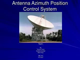
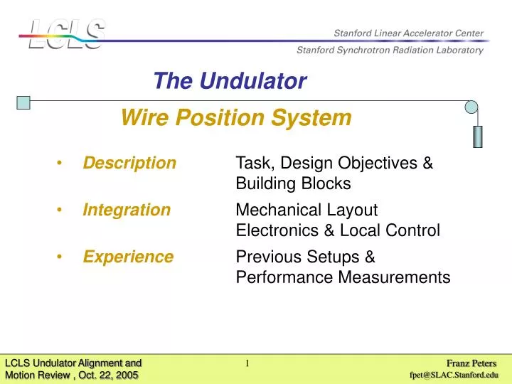
Wire Position System. The Undulator. Description Task, Design Objectives & Building Blocks . Integration Mechanical Layout Electronics & Local Control. Experience Previous Setups & Performance Measurements. Diameter of a human hair. A. Reference. Reference. B. 1.

E N D
Wire Position System The Undulator • DescriptionTask, Design Objectives & Building Blocks • IntegrationMechanical Layout Electronics & Local Control • Experience Previous Setups & Performance Measurements
Diameter of a human hair A Reference Reference B 1 33 Description Task of wire position system…. X-Ray runs: Permanent X & Y Position tracking of the 33 Undulator Segments on a Sub-Micrometer scale. No one has tried that in before. In any case we are the first: The first with success or The first with no success
Description Design objectives… to be successful • Resolution < 100 Nanometer in X & Y direction • Instrument Drift< 100 Nanometer per day • Moving Range+ - 1.5 Millimeter in X & Y direction • Accuracy0.1 % of full Scale • AvailabilityPermanent, no interrupts
Description Principle options, detecting a wire.. • OpticalMicroscope, no Drifts, but Resolution • limited by visible wave length. • CapacitiveThe measurementof small chargeslimits Resolution and increases Drifts • InductiveElectrical noiseand mechanical dimension limits resolution and stability. • MatchedBalanced use of both, electric & magnetic field which meets design objectives mostly.
Description Matched.., works like an RF directional coupler The principle is really simple, but we are shooting for resolution and stability in the region of 10 to the - 5
Description Mechanics 1 2 3 4 • Fixed side wire end station • Tube, as outer conductor • Position Monitor for X & Y direction • Pulley side end station • Weight, used as constant force • The wire: 0.5 mm diameter, • stainless steel, Au plated 5
Description The Monitor 8 mm Monitor GAP 8 Millimeter square Monitor Length 74 Millimeter Cross Section 29 Millimeter square Loops Wire
Description Electronic & Local Control Substations Receiver Crates Quad-ADCs Local Control Ethernet LAN Data Base Local Consol Link to LCLS Controls via TCP / IP
Integration Geometry, - or were are the best places for two wires? - Horizontal Vertical One wire interfer with segment installation Supports necessary on both girder sides Roll data are depend on wire sag stability No interferece with segment installation One common support for both wires Roll data are independend from wire sag stability
Integration Monitor Support Two monitors on each end of each girder Segment removable without interfering WPS X-Pos and Y-Pos, can be measured Roll, Jaw & Pitch can be calculated.
Integration Geometry
1 Undulator segments 8 16 4 8 16 19“ Crate Packages Monitors / 19“ Crate Fault tolerant structure Integration Electronic distribution…Options Legend: 4 Receiver Power 5V,+ - 15V MPX Controller
Integration Fault-tolerant structure ? With 4 Crate in one place we have some redundancy. Failures at any system level does not affect functionality or performance. Why ? Loss of One of 4 Monitors has no effect One of 4 Crates has no effect One of 4 ADCs has no effect One of 2 Computers loss of roll only But, Roll is available also by HLS Result: WPS should never call for a controlled access.
Integration Proposed substation places.. A & B In case of failure…. …no controlled access to the Undulator hall necessary, because of a fully redundant system structure.
Integration Substation Layout No additional heat load to the Undulator hall, because of one built in air condition unit with radiators outside. Receiver Crate
Integration One of two substation One Substation fit between supports under one Undulator segment.
Experience SLAC FFTB WPS at first designed for FFTB Quadrupole position tracking. Runs a few weeks per year over several years. DESY HERA H1 & Zeus IP straight sections under control by WPS 128 Monitors, 4 Wires, 60 Meter Length, each. SLAC Sec10 Performance test with 14 Monitors, 2 Wires, 30 Meter wire length at the SLAC alignment tunnel.
Experience Performance Test – Sector 10 2 Wires 30 Meter Length, 14 Monitors
Experience Four day strip chart of wire to wall motion at Sector 10 Outsite average temperatures 66 69 69 73 Noon to Noon 5 Micromter / division Date Motion of wire end at one side, indicates wall motion on that side
Experience Analysis shows Wall deforming at Sector-10 alignment tunnel over time.
Performance Resolution Test… Air Temperature 0.7 Degree K One Micrometer Wire Motion Wire to wall motion correlates with air temperature cycle
Performance Drift Test 24 hour Ratio (Mon5a / Mon1a) = 19.8 / 0.7 = constant Micrometer Mon5a Micrometer 100 Nanometer Mon1a 24 hour period Correlation of both curves indicates Drift << 100 Nm / day
10 Micrometer / div Performance Overall System Test - 32 Days of wall motion tracking - Access Wire 7 6 5 30 Meter wall 4 3 2 1 0 10 20 30 Days LINAC
Summary As experience has shown…. • Resolution << 100 Nanometer in X & Y direction • Instrument Drift<< 100 Nanometer per day Coming up activities…. • Long distance wire needs further R & D • Final integration into Undulator needs further engineering • Hard- & Software has to be improved for latest updates • System Test &Calibration Facility will be neseccary
End of presentation Finally, were we are? 2 Wires, 14 Monitors– or 10 % of LCLS wire system is now working - 7 Upper Wire 1 One Micrometer / division 7 Lower Wire 1 Hours Watching horizontal Sub-Micrometer wire motions, generated by Air Condition