

Sediment Erosion
E N D
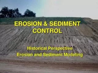
Presentation Transcript
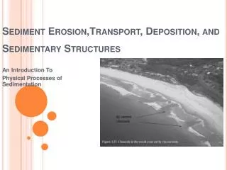
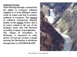
Sediment Erosion Water flowing through a channel has the ability to transport sediment supplied to it from hillslopes and/or erode its banks and bed to produce sediment to transport. The amount of sediment transported depends mainly on the volume of flow; this is of course related to the size of the drainage basin and will fluctuate according to inputs of precipitation. The volume of streamflow, or discharge, is measured in cubic meters (or feet) per second. A graph showing the fluctuation in discharge through time is a HYDROGRAPH. Harry Williams, Geomorphology
storms Hydrograph for Denton Creek near Justin, March-May, 1990. Harry Williams, Geomorphology
Sediment Sources in Denton Creek Drainage Basin. Denton Creek drains portions of Montague, Wise and Denton counties. Clastic sediment sources in the drainage basin include rills, gullies and channel bank and bed erosion. Sediment eroded from the drainage basin is deposited into Grapevine Lake. Harry Williams, Geomorphology
The combination of heavy rain (for example during spring thunderstorms) and sandy ground with low permeability causes surface run-off and erosion in the northern portion of the drainage basin. The erosion creates large gullies and smaller rills. Harry Williams, Geomorphology
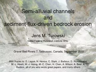
Some gullies in northern Wise county form very large branching gully systems. One branch of a large gully system Harry Williams, Geomorphology
Decatur Krum Denton -> Harry Williams, Geomorphology
Krum area – marls, limestones Harry Williams, Geomorphology
Harry Williams, Geomorphology Gas wells near Krum
North east of Decatur, sandstone Harry Williams, Geomorphology
Limestone bedrock in the drainage basin produces dark clayey soils. The steep banks of small streams are evidence of bank erosion Fragments of the underlying limestone bedrock are exposed in the stream bed, indicating bed erosion. Harry Williams, Geomorphology
South of Decatur – limestones – gas wells Harry Williams, Geomorphology
Close up showing channel bed and bank erosion; little gullying. Harry Williams, Geomorphology
Denton Creek at the Denton-Wise county border. The sand in the creek bed is transported downstream when sufficiently high stream flows occur. A small earthflow caused by recent heavy rain on the bank of the creek. This, and the fallen tree just above the earthflow, is evidence of ongoing bank erosion. Harry Williams, Geomorphology
So, the visible sources are rills, gullies and bank/bed erosion - how is the sediment transported? Generally, 3 main sediment transport modes are recognized: 1. Solution load - dissolved rock carried in the flow; generally, this is higher where much of the flow is derived from groundwater pathways, which allow water to stay in contact with rock for long periods. It is also higher where local bedrock is prone to chemical weathering - e.g. the limestones in the southern portion of Denton Creek drainage basin (this sediment is in effect “invisible”). 2. Suspended load - finer sediment (usually clay and silt) suspended by turbulence in the flow (does not contact bed). 3. Bed load - coarser sediment (sand + gravel) that slides, rolls or skips along the stream bed - amount depends on the tractive force exerted by the flow + resisting force of bed material. hills mountains cliffs ridges Harry Williams, Geomorphology
The USGS collects stream flow and suspended sediment data for selected streams, e.g. the Trinity River south of Dallas, March 1977. valleys date Q(cfs) Q(cms) C(mg/L) Load(ton/day) Load(tonnes/day) 01-MAR-77 3180 90 300 2580 2340 02-MAR-77 2920 82.7 200 1580 1430 03-MAR-77 3230 91.5 450 3920 3560 04-MAR-77 7500 212 1150 26200 23800 05-MAR-77 12000 340 11703660033200 06-MAR-77 13600 385 470 17300 15700 07-MAR-77 15100 428 350 14300 13000 08-MAR-77 15900 450 250 10700 9710 09-MAR-77 16500 467 200 8910 8080 10-MAR-77 16800476 170 7710 6990 11-MAR-77 15500 439 160 6700 6080 12-MAR-77 10500 297 190 5390 4890 13-MAR-77 5850 166 370 5840 5300 14-MAR-77 4070 115 390 4290 3890 15-MAR-77 3430 97.1 360 3330 3020 canyons deltas beaches Harry Williams, Geomorphology
Notice the rising limb of the flow “flushes out” the suspended sediment. Harry Williams, Geomorphology
Where does the sediment go? In the case of Denton Creek, some of it is deposited in the floodplain surrounding the creek, some is deposited on the bed of the creek and the rest ends up in Grapevine Lake. Harry Williams, Geomorphology
Denton Creek floodplain Harry Williams, Geomorphology
Denton Creek floodplain, farther north Harry Williams, Geomorphology
How do we measure stream discharge (Q)? : the volume of water flowing through the creek can be calculated by multiplying the cross-sectional area of flow (A) by the mean flow velocity (V). The cross-sectional area of flow can be found by simply measuring the depth of the stream at regular intervals (e.g. 1 meter) across the channel. Mean flow velocity can be measured by a flow velocity meter. Usually a number of measurements are collected from different positions across the stream and then averaged to find the mean velocity. Harry Williams, Geomorphology
Example discharge calculation (based on Denton Creek): Stream flow 1 meter 3 meters 6 meters 3 meters Cross-sectional area of flow = 9 m2 Mean flow velocity = 0.5 m/s (from velocity meter) Q = 9 x 0.5 = 4.5 m3/s Harry Williams, Geomorphology
How do we measure suspended sediment load (Ss)?: the amount of sediment suspended in the flow can be calculated by filtering the sediment out of a water sample of known volume (e.g. 1 liter). Filtering devices usually employ a vacuum pump to draw the water sample through an extremely fine-mesh filter. filter chamber and vacuum pump Close-up of the suspended sediment filter Harry Williams, Geomorphology
Example suspended sediment concentration and suspended sediment load calculation. Volume of water filtered = 1 liter Weight of dry sediment trapped on filter = 200 milligrams Concentration = 200 mg/L (similar to Trinity River) Suspended sediment load = 200 mg/L x 4.5 m3/s x 1,000 L/m3 = 900,000 mg/s (multiply by seconds in a day) = 77,760,000,000 mg/day (divide by mg in a tonne) = 77.76 tonnes/day The Trinity River example has a typical suspended load of about 4000 tonnes/day, but it is a much bigger stream (typical flow about 200 m3/s). Woodbine sandstone Harry Williams, Geomorphology
How do we measure Bed Sediment Load (Sb)?: coarse sediment (sand, gravel) that remains in contact with the stream bed as it is transported downstream (bed load) can be estimated mathematically. One approach is based on estimating the bed shear stress (the force exerted on the stream bed sediment by the flowing water) and the critical shear stress (the amount of force required to move stream bed sediment). Parameters for the mathematical equations that must be obtained in the field are the slope of the stream (which can be measured by surveyor's level) and the mean size and density of bed sediment (which can be found from a sample of sediment collected from the steam bed). How do we know that bed load is being transported? The tractive force exerted on the bed by stream flow deforms the bed into various sedimentary structures such as ripples and dunes - if these are visible, it suggests that bed load transport is occurring. depositional Harry Williams, Geomorphology
Example bed sediment load calculation (based on Denton Creek):Field measurements: mean depth (d) = 1 meterwater surface slope (s) = 0.0004Mean sediment diameter (D) = 0.001 m Bed Shear Stress (to) = rgds = 1000 x 10 x 1 x 0.0004 = 4 N/m2(where r = density of water; N = Newton - a unit of force; g = force of gravity) Critical Shear Stress (tc) = 0.06g(rs - rw)D = 0.06 x 10 x 1650 x 0.001 = 1 N/m2(where rs = density of sediment; rw = density of water) DuBoys Equation =Qsb (bed load sediment discharge) = A(to - tc) to(A is a constant based on sediment diameter i.e.diameter (mm) 0.125 0.25 0.5 1 2 4A 0.87 0.52 0.31 0.183 0.107 0.064 Qsb = 0.183(4 - 1) x 4 = 2.2 N/m/s= 0.22 kg/m/sThe bed is 6 meters wide, so total Qsb = 1.32 kg/smultiply by seconds in a day =114,048 kg/day = 114.048 tonnes/day Harry Williams, Geomorphology