Download
1 / 11
110 likes | 137 Views
Hysteretic buck regulators, such as LM3475 and LM3485, are fast and simple switching regulators. They use a hysteresis control architecture, which reacts quickly to load transients and does not require frequency compensation. This article explores the switching waveforms and details the ripple voltage across the output capacitor's ESR and ESL.

E N D
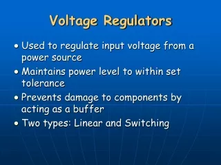
It is one of the simplest switching regulators to implement, and it is also one of the fastest. • Hysteretic control architecture is used on the LM3475 and LM3485, and by some new products that are being developed. • The modulator is simply a comparator with a fixed amount of hysteresis that compares the feedback voltage to a reference voltage.
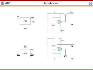
When the feedback voltage exceeds the reference by the hysteresis voltage amount, the comparator output goes low, turning off the switch. • The switch will remain off until the feedback voltage falls below the reference, at which point, the comparator output goes high, turning on the switch.
This topology is extremely fast at reacting to load transients, has a very simple, wide bandwidth control loop that doesn't use an error amplifier, and it doesn't require frequency compensation. • However, unlike a PWM regulator, it's switching frequency isn't set by an oscillator, but is dependent on several variables
When operating in steady-state continuous mode, the inductor current must follow the same charge-balance requirement of a PWM regulator. • As a result, the ripple current equations for this regulator are the same as those for a PWM buck regulator.
This ripple current generates a AC voltage across the output capacitor's ESR and ESL. This results in a triangle-shaped waveform at ΔVOUT that determines the on and off time of the output switch. • The output switch alternates between on and off when the waveform ramps beyond the upper and lower thresholds set by VHYS and the feedback resistors.