Download
1 / 33
330 likes | 510 Views
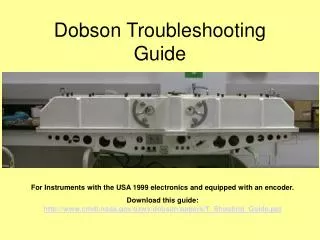
Dobson Troubleshooting Guide. For Instruments with the USA 1999 electronics and equipped with an encoder. Download this guide: http://www.cmdl.noaa.gov/ozwv/dobson/papers/T_Shooting_Guide.ppt. Definitions .

E N D
Dobson Troubleshooting Guide For Instruments with the USA 1999 electronics and equipped with an encoder. Download this guide: http://www.cmdl.noaa.gov/ozwv/dobson/papers/T_Shooting_Guide.ppt
Definitions • Photomultiplier Tube – (PMT): Cold Cathode tube that converts light in to Electrical current through the use of stepped potential grids. • Light knocks electrons off the cathode (High negative potential) • The stepped potential accelerates the electrons towards the anode, and electrons are swept up from the grids (cascade effect). • Electrons hit anode and go to ground through a resistor, producing the signal. • Sensitivity: Amplification factor of the PMT – controlled by the high voltage applied to the PMT • Dynode Chain – Voltage divider circuit giving the stepped potential to the grids in the PMT • Photon-Coupled Interrupter (PCI): A packaged LED-Photo detector pair used as an optical switch on the shutter to synchronize the amplifier output.
Theory of operation The optical part of the instrument produces two light sources, one (the longer wavelength) strong (more intense) -- the other (the shorter) weaker. The primary reason for the difference is the absorption by atmospheric ozone of the shorter. The idea is to reduce the longer light intensity to that of the shorter, by the use of an optical attenuator. The position of the attenuator where the microammeter reads zero represents the amount of ozone through which the shorter wavelength passed. The electronics compare the signals – if one signal is stronger , the meter reads above zero. If the other is stronger the meter reads below zero. The PMT converts the light to an electrical signal the strength of which is directly proportional to the light intensity. The motor spins a shutter that allows only one of the sources to be seen by the PMT at a time. The amplifier is synchronized to the shutter, so the signal from one source is amplified with the sense opposite the other source. The signals are then summed in the microammeter. If the signals are the same strength, the meter reads zero.
What can go wrong? • Most common failures were in the older individual power supplies for the Amplifier and High voltage section (Polytron and Philbrick). We have yet to have a failure with the newer Lambda power supplies, • The Bertan PMT supplies have been used since 1982 without failure. • The resistors in the dynode chain are wire-wound, with 1% tolerance. Some of these very old resistors have opened. If one is to be replaced, a metal film must be used – no carbon resistors, as they generate noise in this kind of circuit. • Some instruments have the wrong size fuses installed, and were blowing the fuses if all three switches were switched on at once. The proper fuse is a 3AMP Slow-Blow. • In 2002, one instrument had a failure in a fuse holder that caused the fuse to blow when the instrument was plugged it, but not switched on.
Getting started. • Start with all switches off, the potentiometer on the micrometer fully on (CW), both PMT (sensitivity) controls turned fully CCW. • Is the Microammeter working? Take the leads to the meter off the Dobson end, and touch the leads to your tongue – the meter should read a small current. • Turn leftmost switch on -- does the motor spin (Sewing machine noise?) • if not check the fuses (3 amp slow blow) – and the power cord. • If the motor spins – we know we have power. • Turn the middle switch on while looking at the meter -- did the meter "kick" as the switch was turned on? • The kick means that the amplifier circuit is working. • No kick, check power supply voltages. • If the meter does kick, then turn on the third switch & attempt a measurement on the zenith -- use the left most PMT control first -- then the right most -- what happened? • If the meter at first is quiet, as the PMT voltage is increased, then suddenly the needle starts flailing back and forth – check the PCI. • If it’s really dead, then remove the lid and check the voltage to the dynode chain. • If the voltage checks good there, then check the resistance of the chain.
Photomultiplier Tube Problems – There aren’t many. • The PMT does not have a hot cathode, so PMT do not “burn out” with age • If a PMT “sees” a bright light, especially with high voltage applied, the cathode can be depleted of electrons – it will become “tired” for a period of time. • If the PMT is given too high a voltage for the light coming in the instrument, it can be momentarily “dead”. It will recover if the voltage is reduced. • A high voltage, and direct sun light can overheat a PMT, and even destroy it – this has not happened in two decades with the Dobson instrument. • The precise position of the PMT in the instrument is critical, and requires a verification of the position if the PMT is replaced.
R-dial (optical attenuator readout) and Q-levers (Wavelength selectors) Q2 Lever R-dial Q1 Lever
Cleaning • The interior optics of the instrument are not to be cleaned, except under direction of Bob Evans (the Dobson guy). • GQP and inlet window can be cleaned, but perform standard lamp tests before and after cleaning. • Inlet window can be cleaned by breathing on it, then wiping with lint-free clean wipe. • If soap is used to clean the GQP, rinse it with rubbing alcohol afterwards. • Sun Director and lens can be cleaned at any time.
Removing the Encoder The encoder connects to the R-dial through a bellows connector, and to the Dobson lid through a ¼-20 bolt. The three big screws are leveling screws – do not loosen these screws, unless the encoder zero/scan is a problem. Access to Setscrew Hold Down Bolt Leveling Screws Encoder Cap Screws Encoder Plate R-Dial
Barrel (Bellows) connector access: Note that there might be two setscrews.
Leveling the Encoder to the R-dial Under the maintenance menu, there is a subprogram to assist in the leveling of the encoder. If the Encoder is leveled to the R-dial correctly, and zeroed correctly, the counter will read 300+/-0.5 with the R-dial at 300.0 position against hairline. If you are attempting level the encoder, first place the encoder bellows connector over the stub shaft on the R-dial mounting thumbscrew, and place the leveling screws in to the sockets on the instrument case. Screw in the hold-down bolt just to the point where the leveling screws remain in the sockets. Then adjust the leveling screws so that 1) the bellows connector is far enough down on the stub shaft for the setscrew(s) to tighten on the shaft and 2) the lower ends of the four cap screws that hold the encoder to the plate are equal distant from the R-dial. This a process that requires some back and forth with the leveling screws and the hold-down bolt. The hold-down bolt should be tight when done and BEFORE tightening the setscrews in the bellows connector. This distance should be the same for all four cap screws.
Problems with Encoder/Counter • If you zero the R-dial, and turn it to 300 -- what does it read? • If you then turn it back to zero, is it still zero? If not, then the most likely problem is a loose setscrew in the barrel coupler between the bolt that the holds the R-dial to the shaft -- there might be as many a four setscrews, two top and bottom. • The bolt that the holds the R-dial to the shaft might be loose. • Plate with the three legs is loose. • If it is still very close to zero, and you get the same reading when you turn back to 300 as you did before, then something not level (review the slide before this one -- if it is very, very repeatable, and it's a large difference from 300, then suspect the program of the counter. • Electrical connections on the back of the counter can be a problem -- BE CAREFUL OF THE AC CONNECTION ON LOWER LEFT AS VIEWED FROM THE BACK. • The inline connection from the encoder to the counter can get loose – check that connection.
There are pins at each end of the lid (under the rings) that are designed to fit in to sockets in the base. When removing the lid, the lid must be lifted high enough to clear the socket. When replacing, the pins must enter the sockets. If the lid is raised or lowered without being approximately parallel to the base, the pin/socket will “jam”.
Removing the lid – After removing the encoder. Lift the lid, keeping it parallel to the base, until it is about 12 inches above the base. Move the lid to a secure place. If you must place it on the floor, place it on a clean cloth. Remove the nuts on these studs before attempting to remove the lid.
AC Power and switches – each section is independently switched. Amplifier Section Fuses, 3Amp Slow-Blow Shutter Motor High Voltage Section
Block Diagram of Electronics High Voltage section PMT control PMT Light Amplifier Section (Gain=1000) Motor and Shutter PCI AC power
Block diagram of the amplifier circuit. Input from PMT Power to and signal from PCI Amplifier Board Lambda SWT30-522 Power Supply AC power DC power Output to meter
Block Diagram of the High Voltage Section. Bertan PMT-10CN-3 DC-DC Converter Lambda SWT30-522 Power Supply AC power DC power 0 to –1000 output to PMT Voltage Control input
Input from PMT Circuit 1999 vintage amplifier circuit Output to Micro-ammeter Power Supply Connector To PCI detecting shutter position
Locating the amplifier The amplifier section is located inside the instrument behind the spine on the left. There are two small holes to view the power-on LED and PCI status LED located on the amplifier board inside the box.
Amplifier Section Power LED – if this is on, there is power to the board PCI LED – This LED will flash if the shutter is rotated. This shows that the PCI and Circuit is working. Amplifier Board OP-07 Lambda SWT30-522 Power Supply
Another view of amplifier card Power from Lambda Connection to microammeter Connection to PCI
Quick Test of the amplifier With the middle switch on, watch the microammeter and touch the back contact of the AC coupling capacitor. The meter should show the 60HZ from your finger.
PMT Circuit, Showing Dynode chain and AC coupling Cap. Amplifier Circuit Dynode Resistors on other side of Board High Negative Voltage ~200 to 900VDC
Measuring the PMT Voltage First, Put Black electrical tape over this slit. Measure between these two points. Range should be – 0 to ~900 volts (There is an inline resistor in many of the circuits to limit the max voltage.) If the max voltage is 1000+, think open resistor in dynode chain Cover removed
Bottom View – the instrument must be tilted back on to bean bags or other supports -- it’s top heavy. The Shutter motor is mounted on this plate The high voltage is mounted on this plate
High Voltage section mounted on right bottom plate. High voltage output AC input
View into high voltage bay. 22M ohm bleeder Resistor
Motor and shutter removed from instrument. These three screws hold motor bracket in place (3rd screw under cap. in this picture) This shutter drive has a spare belt installed. Screws for adjusting belt tension under here.
Before removing shutter and motor…. These four screws must be removed.
Shutter wheel and PCI Shutter must not hit the PCI – check by rotating shutter by hand after re-installing shutter and motor.